Toner supplying device, toner supplying process, image forming apparatus, and image forming process

a toner and gas mixture technology, applied in electrographic process equipment, instruments, optics, etc., can solve the problems of secondary toner particles deteriorating image quality, air fed into toner containers cannot satisfactorily break secondary toner particles in toner containers, and adverse effects on images, etc., to achieve enhanced fluidity of mixture, control the bulk density of toner and gas mixture, and improve image quality

Inactive Publication Date: 2005-11-03
RICOH KK
View PDF18 Cites 37 Cited by
  • Summary
  • Abstract
  • Description
  • Claims
  • Application Information

AI Technical Summary

Benefits of technology

[0018] Accordingly, the object of the present invention is to provide toner supplying devices, toner supplying processes, image forming apparatuses, and image forming processes that may control the bulk density of the mixture of toner and gas more efficiently thereby the fluidity of the mixture is enhanced, the fluidity may be maintained uniformly within toner conveying lines even when toner resides for a long period, higher image quality may be obtained even under prolonged usage of image forming apparatuses, and toner may be conveyed smoothly at the staring operation even after longer stoppage.
[0029] In accordance with the present invention, a porous member is disposed near the toner outlet, and a gas is fed into the toner containing portion through the porous member. Namely, the gas is injected through porous material rather than from a larger aperture such as of pipe, therefore, the gas can be introduced in finely dispersed condition and from larger injecting area into the toner containing portion. Consequently, a mixture of the toner and the gas having a bulk density of 0.2 to 0.3 g / cm3 can yield stably and uniformly even immediately after the gas is injected. On the contrary, in the case of a nozzle having a larger aperture, the mixture of toner and gas usually exhibits a bulk density of 0.2 to 0.5 g / cm3 and the bulk density is unstable with time and ununiform throughout the mass of toner.
[0030] Such lower and uniform bulk density of the mixture of toner and gas may lead to higher fluidity, which allows stable and efficient image formation processes and also higher and stable image quality.
[0031] Further, such higher fluidity may allow transportation of the mixture of the toner and the gas by use of pressure from lower site to higher site, which affords various margin with respect to design and / or layout of image forming apparatuses.

Problems solved by technology

In such toner supplying devices, there exist some problems that toner agglomerates generate due to toner softening derived from intense rubbing of toner between the movable member and the pipe wall, and dynamic properties of toner changes due to separation of external additives from toner surface, resulting in adverse effects on images.
However, such toner conveying devices suffer from a problem that the air fed into the toner container cannot satisfactorily break secondary toner particles in the toner container.
Namely, the air fed near the nozzle forms larger bubbles in the mass of toner within the toner container; the bubbles move and / or burst in the mass of toner and thus the mixture of air and toner is formed, which exhibits relatively high fluidity; however, the secondary toner particles that have been present prior to the air feeing hardly break by the air feeding into the toner container, consequently, the secondary toner particles tend to deteriorate image quality.
This problem is serious with respect to nowadays highly fine and precise images since toners are required that have smaller particle sizes.
However, the device also employs a screw pump similar to that of JP-A Nos. 2003-330218 and 2004-4394 described above; thus the toner supplying device suffers from similar problems described above.
However, such a toner conveying device suffers from a problem that the air fed into the toner container cannot satisfactorily break secondary toner particles in the toner container as described above.
Further, in the toner conveying device, the conveying line often clogs and the operation is disturbed when the image forming apparatus is stopped for a few days for example, which is resulted from solidification or blocking of toner within the conveying line.
Further, the mixture of toner and air formed by the toner conveying devices in the prior art may not exhibit sufficient fluidity when the conveying distance is longer or when the mixture is to be conveyed from lower site to higher site, which limits the design and / or layout of image forming apparatuses.
In addition, as for the reason of clogging within conveying lines, the toner flowing into the conveying pipe has various bulk densities depending on stirring conditions and residence times; the toner with higher bulk densities tends to clog within the conveying pipe.
However, the lower bulk density is often no more than temporary; that is, the bulk density tends to increase rapidly under sucking action.
When allowing to stand the toner a few days in a condition of higher bulk density within conveying pipes for example, larger blocks of toner are likely to yield, resulting in clogging of the conveying pipes.
However, frequent air blows cannot successfully prevent the clogging in most cases.
Consequently, toner with higher bulk densities flows into conveying lines, and when allowing to stand the toner a few days, larger blocks of the toner are likely to yield, resulting in clogging of the conveying pipe.

Method used


Image

  • Toner supplying device, toner supplying process, image forming apparatus, and image forming process
  • Toner supplying device, toner supplying process, image forming apparatus, and image forming process
  • Toner supplying device, toner supplying process, image forming apparatus, and image forming process

Examples


example 1

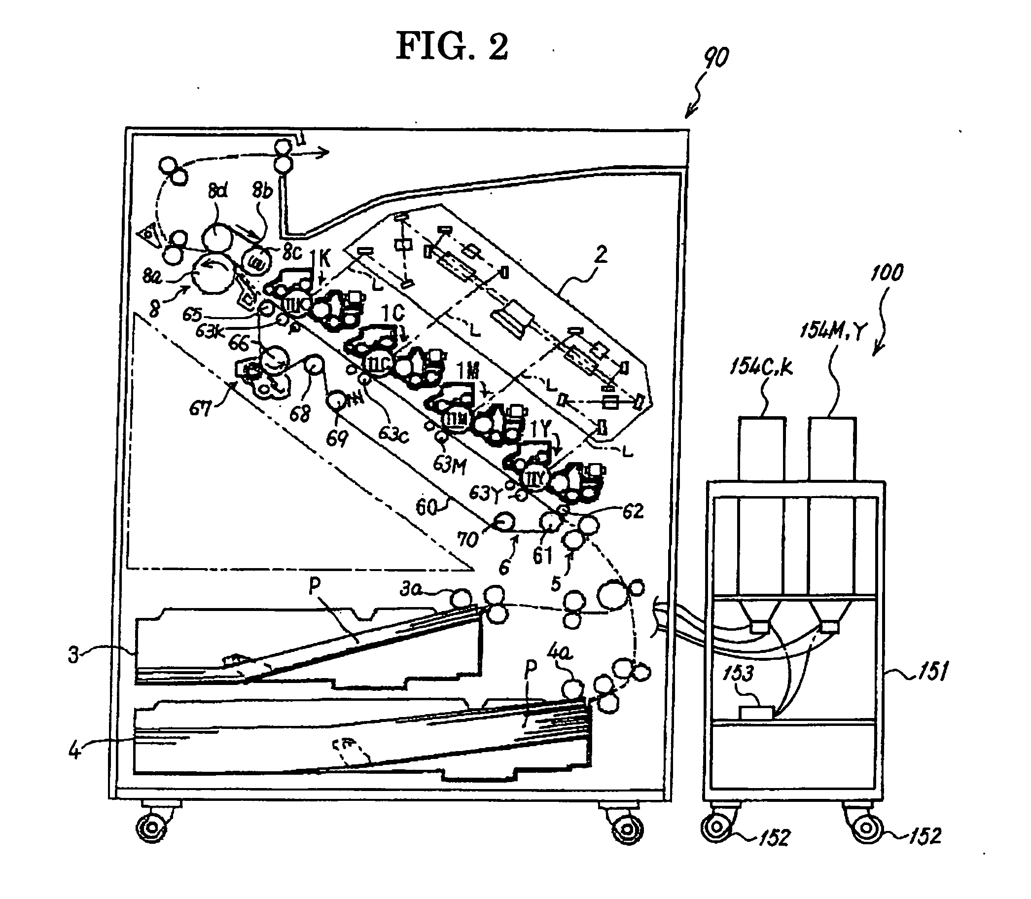
[0082] The present invention will be explained with respect to a tandem color-laser printer (hereinafter, referring to as “exemplified printer”), which is an image forming apparatus equipped with the toner supplying device according to the present invention.

[0083]FIG. 2 is a schematic view that exemplarily shows a printer construction of an image forming apparatus according to the present invention. The exemplified printer is equipped with printing section 90 and toner storage section 100, which are movable independently.

[0084] The printing section 90 is equipped with four image recording portions 1Y, 1M, 1C, and 1K to form four images of yellow (Y), magenta (M), cyan (C), and black (B) respectively. Further, printing section 90 is equipped with light-writing unit 2, paper-feeding cassettes 3 and 4, resist roller pair 5, transferring unit 6, fixing unit 8 of belt fixing, and paper-discharging tray. In addition, a manual feeding tray, toner-supplying container, exhausted toner bott...

example 2

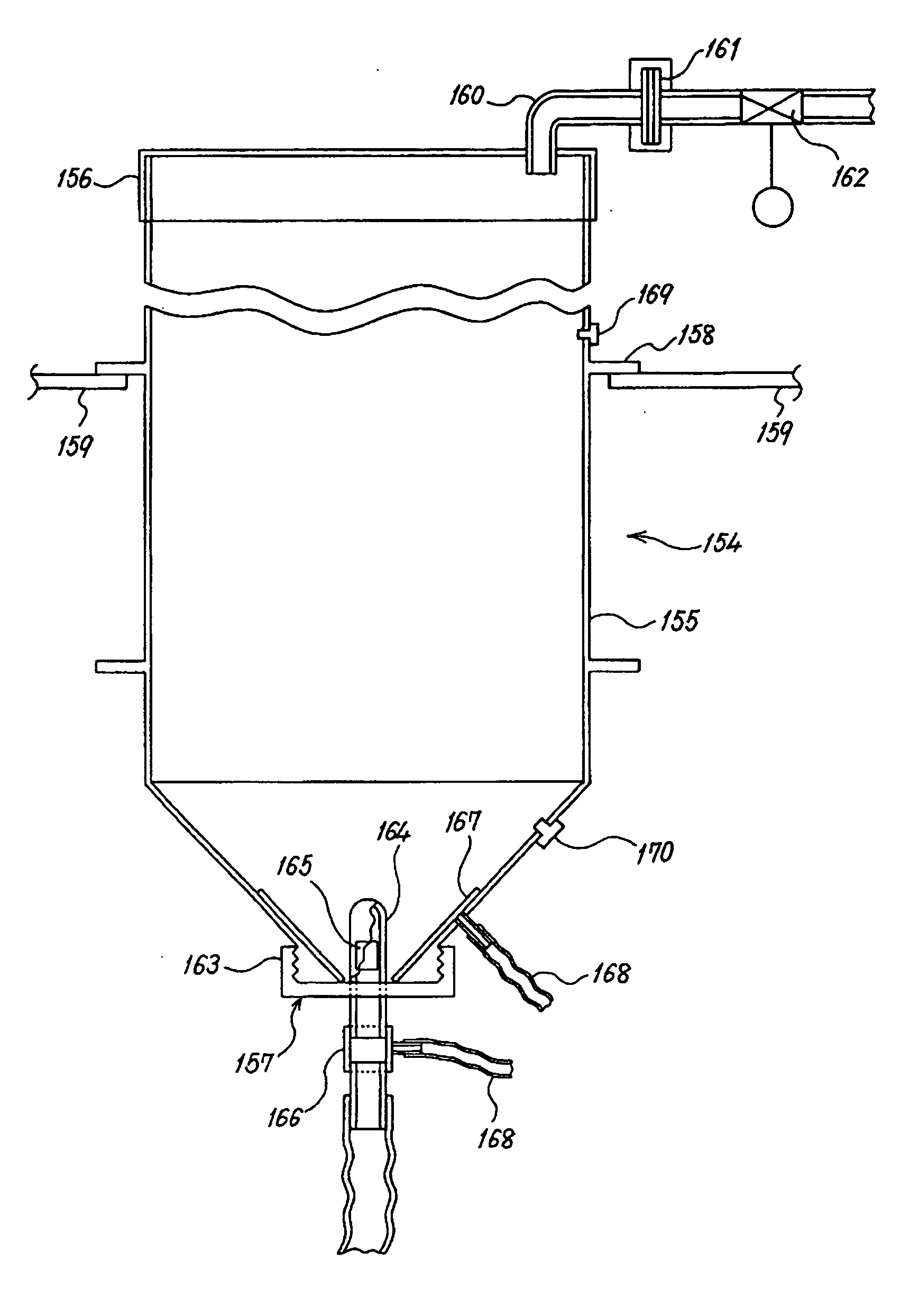
[0155] Another toner conveying device and image forming apparatus will be explained that is equipped with the toner conveying device. FIG. 10 exemplarily shows a toner supplying device according to the present invention.

[0156] In FIG. 10, reference number 111 indicates a toner containing portion made of polyethylene resin to be attached to a copier. A plug 116 formed of elastic material is attached to the lower part of toner containing portion 111. Nozzle 119 is inserted into toner containing portion 111 through plug while maintaining sealed condition by action of the elastic material. Plug 116 is cut crosswise at the central portion into which nozzle 119 is inserted. At the tip end of nozzle 119, a mesh can be attached which act to reside the agglomerated toner till the agglomeration is broken. A porous sintered glass having an average pore size of 10 μm and a thickness of 5 mm, for example, is mounted to around nozzle 119 to form a gas ejecting device 115, which eject gas toward ...

example 3

[0163] Toner containing portion may be vibrated in order to assure the performance of toner supplying device according to the present invention, as explained in the following.

[0164] The inventive toner supplying device shown in FIG. 14 further comprises a vibrating device 122 on the outer surface of the toner containing portion and near the nozzle 120 in order to improve the formation of fluidized bed. The toner supplying device shown in FIG. 14 is substantially the same as that shown in FIG. 10, except for adding the vibrating device 122. The same reference numbers in FIG. 14 indicate the same objects with those of FIG. 10.

[0165] The vibrating device 122 may be a sonic vibrator that contacts with outer surface of the container containing a toner when the toner is supplied to the image forming apparatus. Alternatively, the vibrating device 122 may be a hammer vibrator which contacts with outer surface of the container containing a toner when the toner is supplied to the image form...


PUM


Abstract

The object of the present invention is to provide toner supplying devices, toner supplying processes, and the like that control the bulk density of the mixture of toner and gas more efficiently thereby the fluidity of the mixture is enhanced, and the high fluidity may be maintained for a long period. The object is attained by a toner supplying device that comprises a toner containing portion configured to store a toner, a toner outlet configured to discharge the toner from the toner containing portion, a conveying pipe configured to convey the toner, and a gas feeding unit configured to feed a gas, wherein the toner supplying device supplies the toner from the toner containing portion to an image forming unit of an image forming apparatus, a porous member is disposed near the toner outlet, and the gas is fed into the toner containing portion through the porous member.

Description

BACKGROUND OF THE INVENTION [0001] 1. Field of the Invention [0002] The present invention relates to toner supplying devices appropriately utilized for image forming apparatuses such as printers, facsimiles, copiers, hybrid apparatuses, in particular electrophotographic image forming apparatuses; and toner supplying processes, image forming apparatuses, and image forming process that utilize the toner supplying apparatuses respectively. [0003] 2. Description of the Related Art [0004] Toner supplying devices are widely utilized in image forming apparatuses such as printers, facsimiles, and copiers in order to convey toner through conveying pipes usually equipped with a movable member such as a screw auger. In such toner supplying devices, there exist some problems that toner agglomerates generate due to toner softening derived from intense rubbing of toner between the movable member and the pipe wall, and dynamic properties of toner changes due to separation of external additives fro...

Claims


Application Information

Patent Timeline
Patent Type & Authority Applications(United States)
IPC IPC(8): G03G15/08
CPCG03G2215/0678G03G15/0877G03G15/0879G03G15/0853
Inventor AMANO, HIROSATOSERIZAWA, MASAKIHANADA, MAKOTO
Owner RICOH KK
Why Eureka
Try Eureka