A cutting insert, a cutting tool, a shim and a method

Inactive Publication Date: 2005-11-03
SECO TOOLS AB
View PDF9 Cites 28 Cited by
  • Summary
  • Abstract
  • Description
  • Claims
  • Application Information

AI Technical Summary

Benefits of technology

[0010] It is also desirable to provide a tool, a cutting insert, a shim and a

Problems solved by technology

A problem, which is created at use of round cutting insert, is that the cutting insert tends to be twisted arbitrary in the holder both by the operator and by the cutting forces.
Round cutting inserts have a problematic chip-breaking pattern.
Roun

Method used


Image

  • A cutting insert, a cutting tool, a shim and a method
  • A cutting insert, a cutting tool, a shim and a method
  • A cutting insert, a cutting tool, a shim and a method

Examples


Embodiment Construction

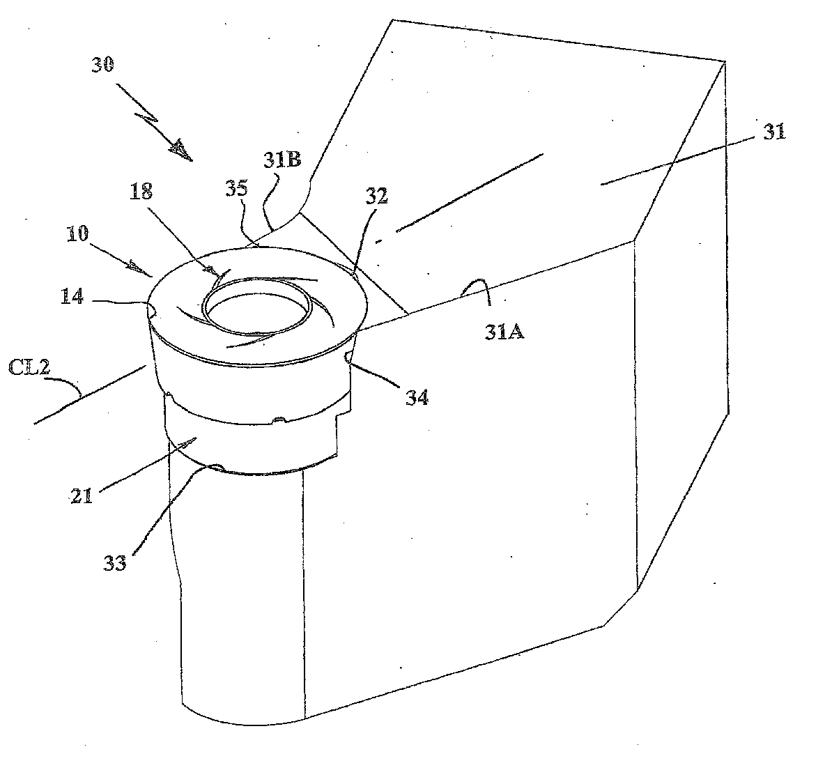
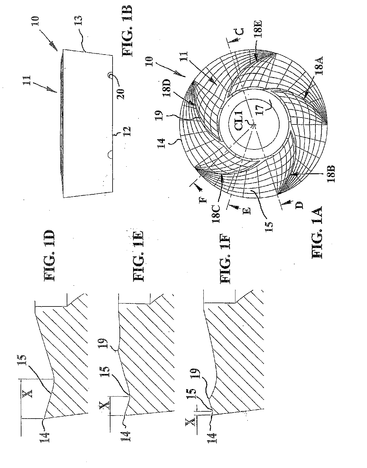
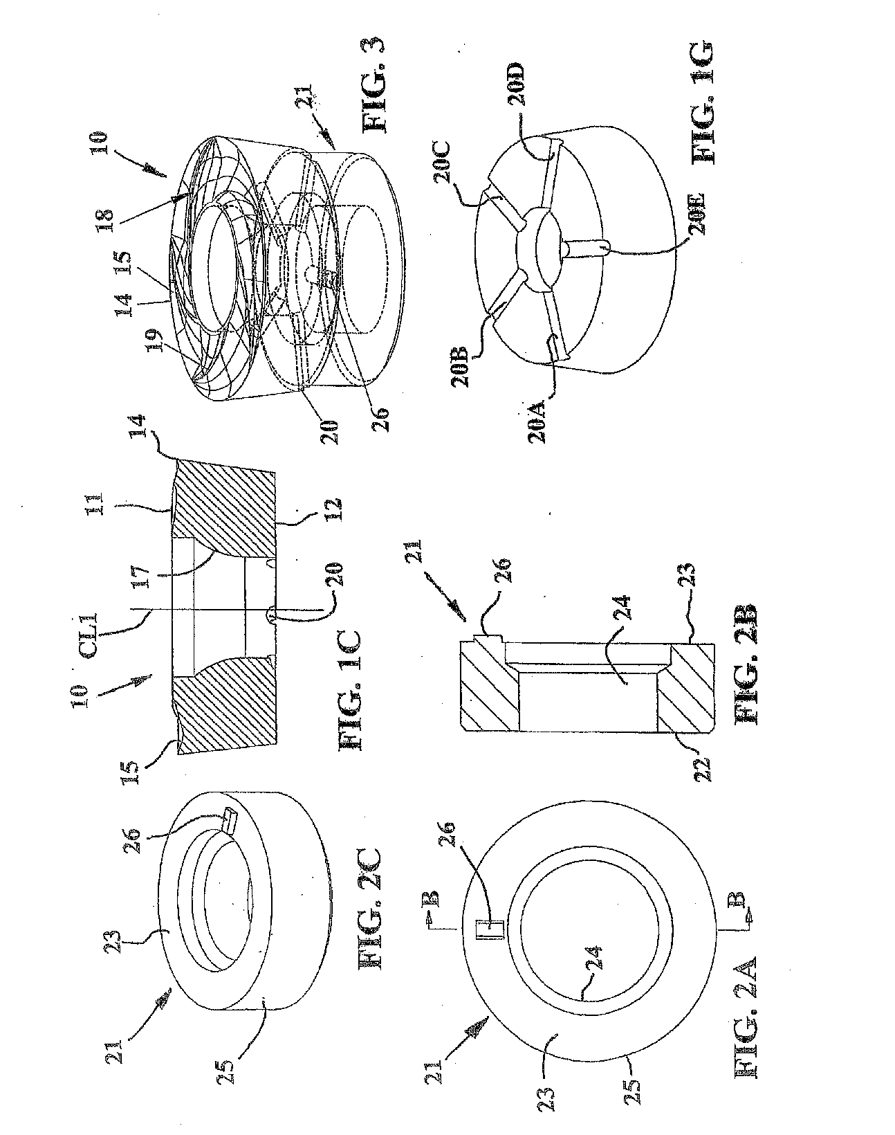
[0030] The cutting insert 10 in FIGS. 1A-1D has a substantially circular basic shape and comprises an upper side 11, a lower side 12 and a truncated, substantially conical, edge surface 13, which substantially connects the upper 11 and lower sides 12. The cutting insert 10 side 11 is shown as a grid, which is not visible on the physical specimen of the cutting insert.

[0031] Said grid shall substantially be understood as altitude contour. The cutting insert 10 is single-sided and has a positive geometry, that is the edge surface 13 forms an inner acute angle with the upper side 11. The upper side 11 comprises a chip surface 15 while the edge surface 13 constitutes a clearance surface. The upper side 11 comprises a circular cutting edge 14, localized at the periphery of the cutting insert 10. The chip surface 15 is substantially concave and slopes radially inwardly and downwardly from the cutting edge 14 and then rises above the plane of the cutting edge. The cutting edge 14 is provi...


PUM


Abstract

The present invention relates to a cutting insert, a cutting tool for chip removing machining, a shim as well as a method for mounting a cutting insert. The cutting tool includes a holder equipped with at least one insert pocket including a base surface, at least one circular shim including opposite first and second surfaces, and at least one cutting insert, which includes a circular cutting edge formed at a transition between an upper side and an edge surface of the cutting insert. The upper side includes a chip surface comprising at least one chip breaker portion and the edge surface includes a clearance surface. The shim is provided between the base surface of the insert pocket and the cutting insert. The cutting tool includes a clamping arrangement for holding its parts together. The chip breaker portion is provided at a varying distance from the associated cutting edge. The shim and the cutting insert include at least one pair of cooperating projection and recess for indexing of the cutting insert. The pair of cooperating projection and recess is provided to be positioned in a position relative to a reference line or axis of the tool in order to orient the chip breaker portion in the chip surface to a desired relative position. The number of chip breaker portions is a multiple of the number of projections or recesses.

Description

[0001] The present application is a continuation of PCT / SE2003 / 002002, filed Dec. 17, 2003, which claims priority of SE 0203865-1, filed Dec. 20, 2002, both of which applications are incorporated by reference.BACKGROUND AND SUMMARY [0002] The present invention relates to a cutting insert, a cutting tool for chip removing machining, a shim as well as a method for mounting a cutting insert according to the preambles of the independent claims. [0003] In tools for metal machining round cutting inserts of hard and wear resistant material such as cemented carbide are often used. A problem, which is created at use of round cutting insert, is that the cutting insert tends to be twisted arbitrary in the holder both by the operator and by the cutting forces. Through a number of documents, for example U.S. Pat. No. 6,146,060, U.S. Pat. No. 5,478,175, U.S. Pat. No. 3,383,748 and U.S. Pat. No. 5,346,336 different solutions are proposed in order to lock the round cutting insert in the holder. Rou...

Claims


Application Information

Patent Timeline
IPC IPC(8): B23B27/16
CPCB23B27/1618B23B2200/125B23B2200/165B23B2200/3627B23B2205/16Y10T407/245B23C2200/167Y10T407/23Y10T407/24Y10T407/235B23B2260/0725
Inventor JONSSON, MATS
Owner SECO TOOLS AB
Why Eureka
Try Eureka