
Method of transferring a packet switched to a circuit switched call

a packet switched and circuit switched technology, applied in the field of transferring packet switched communication to circuit switched, can solve the problems of significant gaps in communication flow with the mobile station, no mechanism currently exists for providing such a seamless transition, and substantial uninterrupted communication from and to the mobile station

Active Publication Date: 2005-11-03
WSOU INVESTMENTS LLC +1
View PDF8 Cites 37 Cited by
  • Summary
  • Abstract
  • Description
  • Claims
  • Application Information

AI Technical Summary

Benefits of technology

[0011] The present invention provides for transferring a packet switched call to a circuit switched call without first terminating the packet switched call. As a result, the transition takes place quickly without requiring the user to manually re-establish the call. This invention has utility in any system that cannot maintain a packet switched call due to unavailability of appropriate network resources whereas circuit switched capability does exist.

Problems solved by technology

To the mobile station user, this transition is seamless in that the communication from and to the mobile station is substantially uninterrupted.
However, no mechanism currently exists for providing such a seamless transition when the mobile station moves from a network or portion of a network providing packet switched communication (e.g., Voice-over-IP or VoIP) to a different network or portion of a same network that cannot maintain a packet switched call, for example, due to unavailability of appropriate network resources for packet switch communication, but including appropriate resources for circuit switched.
This situation is expected to be common during a transition period while packet switched systems with sufficient QoS support are being deployed but are not yet available ubiquitously.
As a result, a significant gap in communication flow with the mobile station occurs.
In some cases it may not even be possible to establish another call between the same parties from a circuit switched network, for example, when the end point in the packet switched network is not known by or associated with a telephone number.

Method used


Image

  • Method of transferring a packet switched to a circuit switched call
  • Method of transferring a packet switched to a circuit switched call
  • Method of transferring a packet switched to a circuit switched call

Examples


Embodiment Construction

[0015] For purposes of explanation only, the embodiments of the present invention will use the example of transferring a packet switched call (e.g., a Voice-over-IP or VoIP call) carried over a cdma2000 3G1X-EVDO based network (hereinafter the DO network) to circuit switched call carried over a cdma2000 3G1X-EVDV based network (hereinafter the DV network).

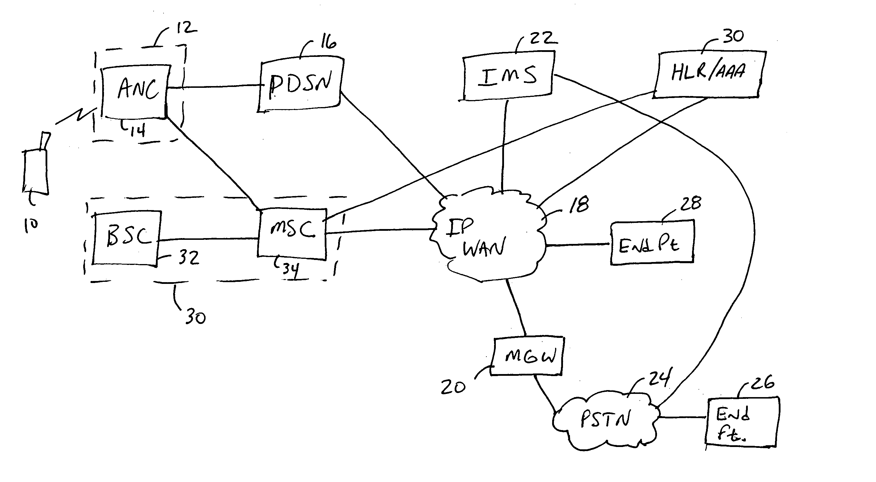
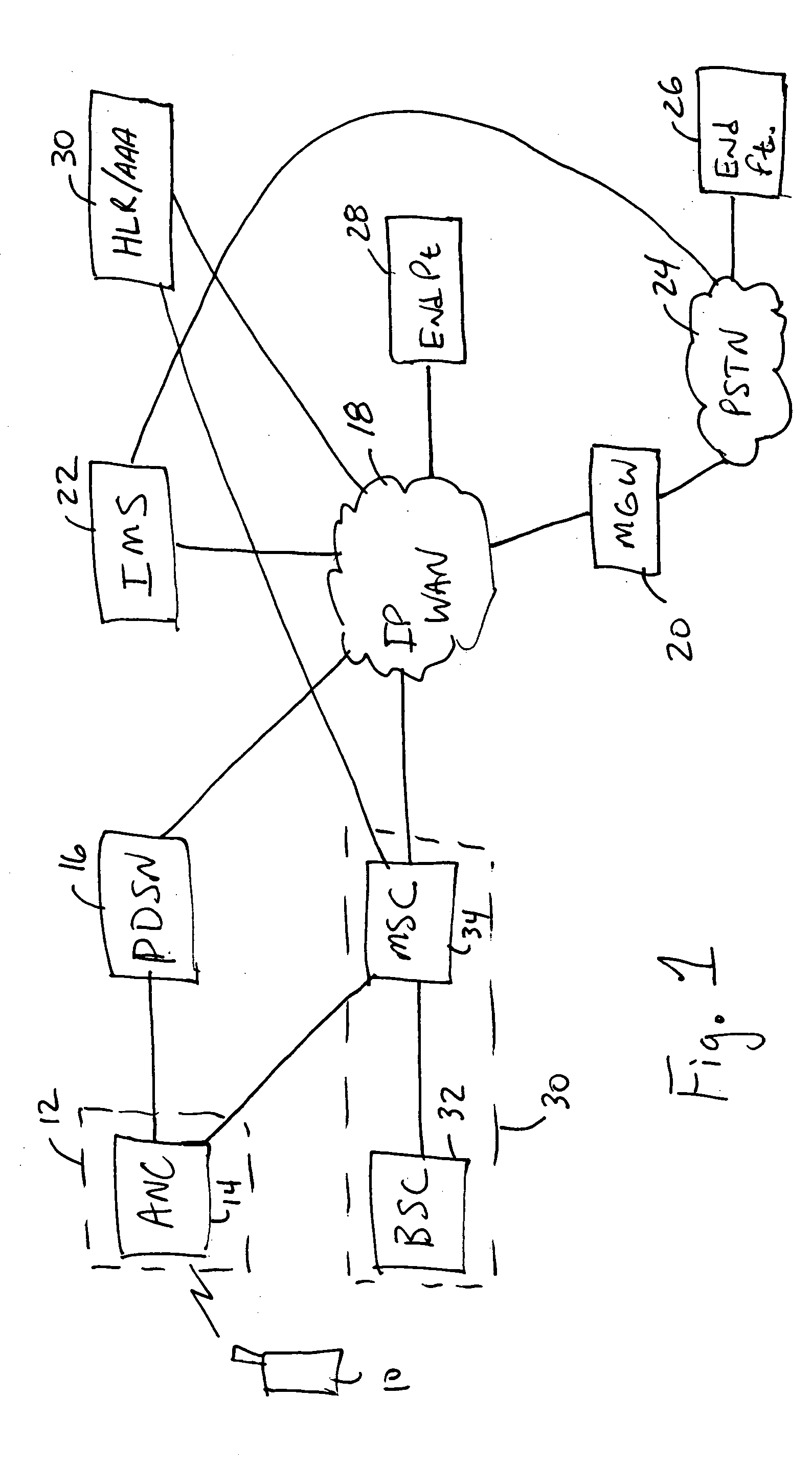
[0016]FIG. 1 illustrates a system architecture of a cdma2000 3G1X-EVDO network and a cdma2000 3G1X-EVDV network and their relationship with a packet call controller (e.g., an IP multimedia subsystem (IMS) as shown). As shown, a mobile station or user equipment (UE) 10 communicates with a high rate packet data (HRPD) access network controller (ANC) 14 in a DO network 12. The terms mobile station and user equipment will be used interchangeably and generically throughout this application as any device (phone, PDA, computer, etc.) capable of wireless communication, and should not be interpreted as limited to a particular standard. The...


PUM


Abstract

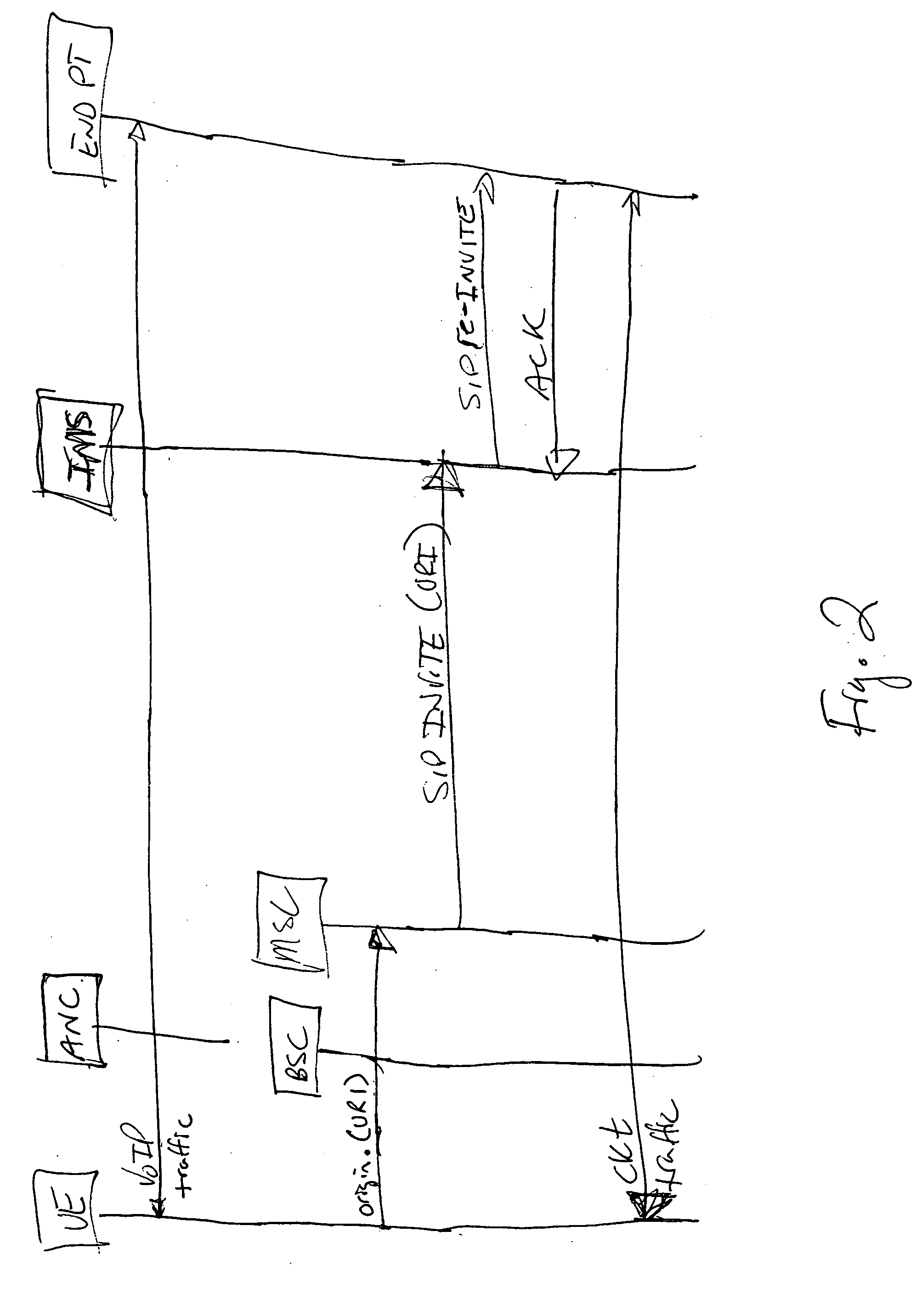
In the method, a packet call controller establishes a bearer path between the end point and the second network when a call transfer request associated with the mobile station is received from a network providing circuit switched communication. The call transfer request is triggered by a circuit voice call origination from the mobile station that includes an identifier that the packet call controller uses in recognizing that the call transfer request requests transfer of a packet switched call to a circuit switched call on the network.

Description

BACKGROUND OF THE INVENTION [0001] 1. Field the of the Invention [0002] The present invention relates to telecommunication; and more particularly, methods for transferring packet switched communication to circuit switched. [0003] 2. Description of Related Art [0004] When a mobile station moves within a wireless network, one communication station (e.g., base station, etc.) may transfer (e.g., according to well-known call handoff procedures) the communication needs of the mobile station to another communication station in the network. To the mobile station user, this transition is seamless in that the communication from and to the mobile station is substantially uninterrupted. [0005] However, no mechanism currently exists for providing such a seamless transition when the mobile station moves from a network or portion of a network providing packet switched communication (e.g., Voice-over-IP or VoIP) to a different network or portion of a same network that cannot maintain a packet switc...

Claims


Application Information

Patent Timeline
Patent Type & Authority Applications(United States)
IPC IPC(8): H04W36/14H04W80/10
CPCH04W36/0022Y10S370/902H04W80/10H04W36/00224
Inventor EJZAK, RICHARD PAUL
Owner WSOU INVESTMENTS LLC
Learn More