
Pacemaker evaluation method and apparatus

Inactive Publication Date: 2005-11-03
USCOM
View PDF60 Cites 0 Cited by
  • Summary
  • Abstract
  • Description
  • Claims
  • Application Information

AI Technical Summary

Benefits of technology

[0005] It is an object of the present invention to provide for a method and apparatus for tuning the operation of pacemaker units to achieve more optimal results.

Problems solved by technology

Further, during periods of rest, the pacemaker device may decrease the heart rate.

Method used


Image

  • Pacemaker evaluation method and apparatus
  • Pacemaker evaluation method and apparatus
  • Pacemaker evaluation method and apparatus

Examples


Embodiment Construction

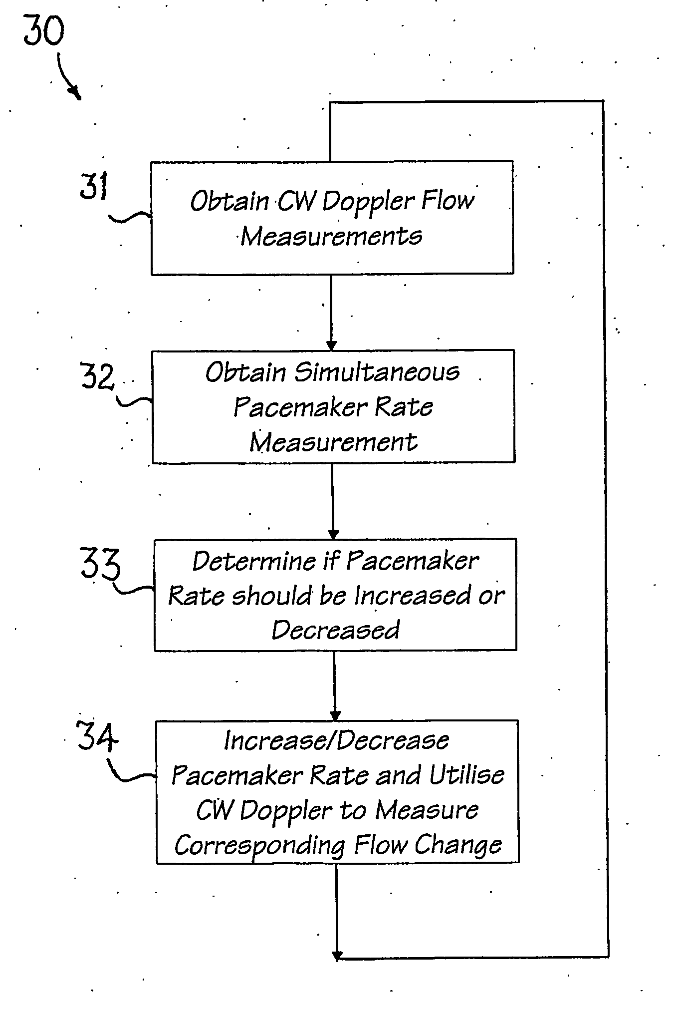
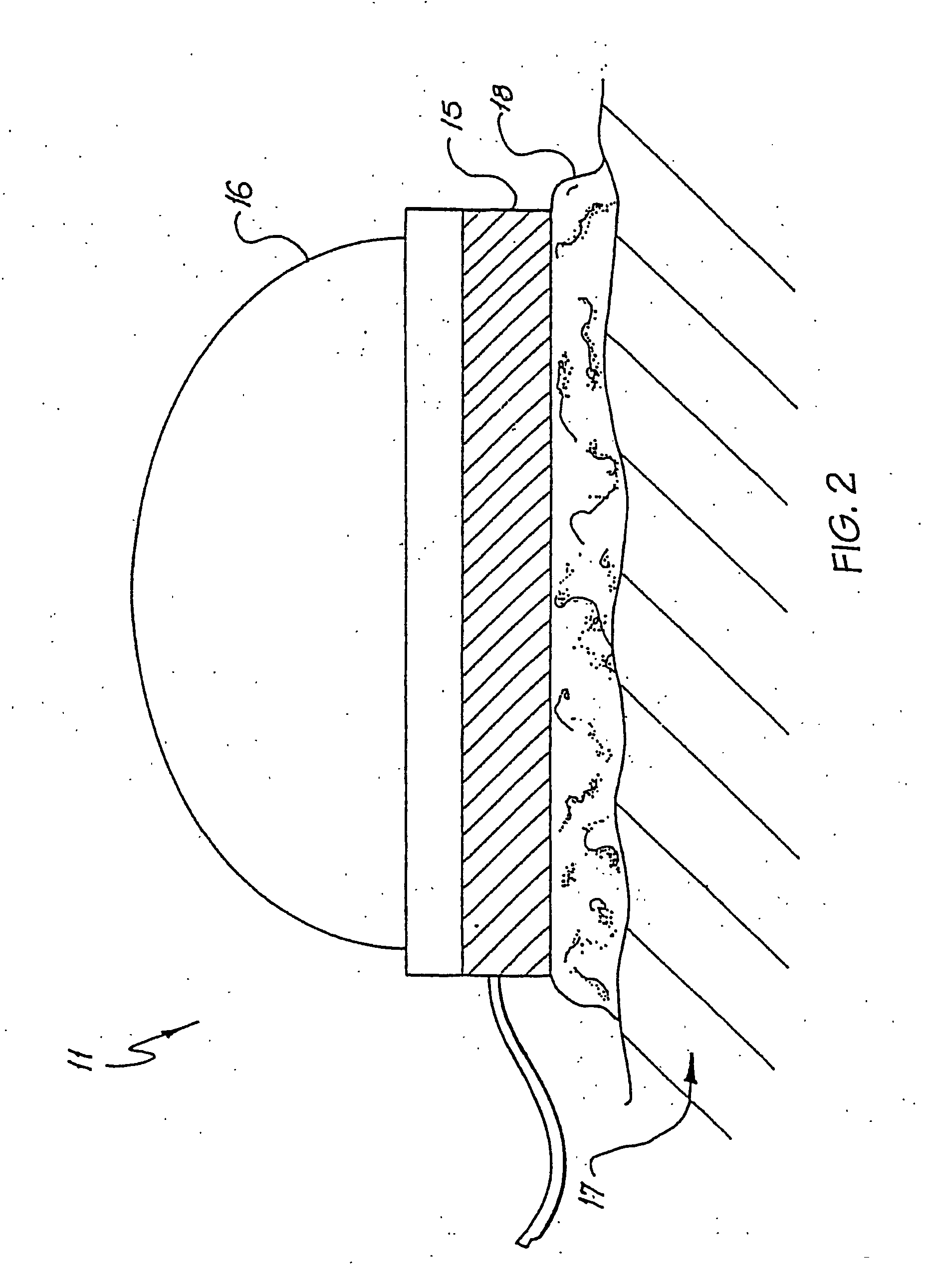
[0016] In the preferred embodiment, continuous wave ultrasound techniques are utilised to transcutaneously measure the cardiac output of a heart operating with a cardiac prosthetic pacing device. Through utilisation of ultrasound techniques, a measurement of cardiac output can be obtained as a function of rate and volume. The ultrasound techniques also provide a measure of stroke volume thereby providing information for optimisation of settings of the pacemakers.

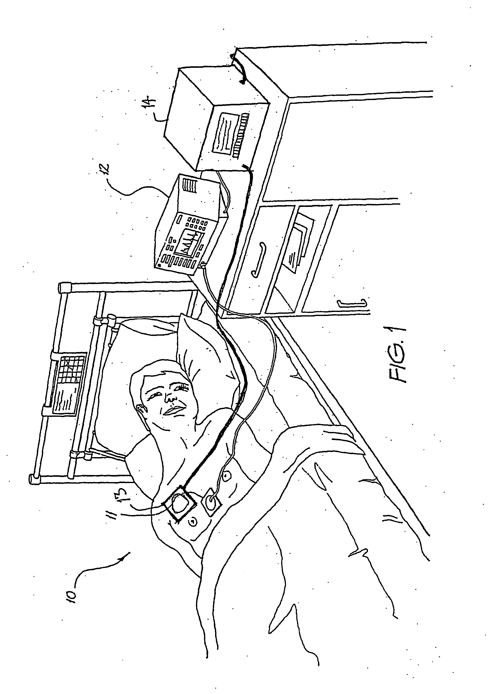
[0017] Turning initially to FIG. 1, there is illustrated one arrangement utilising the preferred embodiment. In this arrangement, a patient 10 has attached two non-invasive monitoring devices 11-13. Each of the two devices 11-13 are interconnected to aprocessing and display unit eg. 12, 14. Each of the units 12, 14 includes an internal computer processing means, a display and a series of control buttons for controlling the functionality of the device. Each of the devices 12, 14 are further networked to a base station or the...


PUM


Abstract

A method of optimizing the performance of a cardiac prosthetic pacing device including monitoring, optionally transcutaneously or non-invasively, the flow output from the heart; optionally using a continuous wave Doppler ultrasound device, followed by adjusting the timing of said cardiac prosthetic pacing device so as to optimize the flow from the heart under operational condition, optionally including different pharmacological conditions.

Description

FIELD OF THE INVENTION [0001] The present invention relates to the field of cardiac pacemakers and, in particular, discloses a methodology and apparatus for selectively tuning a pacemaker-type device. BACKGROUND OF THE INVENTION [0002] Pacemaker devices normally consist of the pacemaker control unit containing a power cell such as a battery, a pacemaker lead and end electrodes which are attached to the heart so as to stimulate the heart into action at certain timed occurrences. Recent advances in pacemaker technology include providing for fully programmable capabilities. Modern pacemaker devices such as those available from Medtronic Inc often include on board processing and storage capabilities and the latest models allow for external communication with reader and control devices located outside the body for telecommunications. Examples of such systems are disclosed in U.S. Pat. No. 6,577,901 to Thompson, U.S. Pat. No. 6,580,946 to Struble and U.S. Patent Application 2003 / 0100925 t...

Claims


Application Information

Patent Timeline
IPC IPC(8): A61B8/06A61N1/37A61N1/372
CPCA61B8/06A61N1/37217A61N1/37
Inventor PHILLIPS, ROBERT ALLAN
Owner USCOM
Learn More