Tightening band, and tightening band producing method

Inactive Publication Date: 2005-11-10
NAGATA KENTARO +3
View PDF19 Cites 1 Cited by
  • Summary
  • Abstract
  • Description
  • Claims
  • Application Information

AI Technical Summary

Benefits of technology

[0039] In this way, by forming a pattern on the inner periphery of the band main body of the tightening band, slip on the tightened member can be prevented and the workability can be improved. Further, by forming a pattern, the range of extension and contraction widens, a proper tightening strength can be easily obtained, and the applicable range of the diameter of a member to be tightened by the tightening band can be widened. That is, one type of tightening band can be used for a plurality of types of boots whose diameters at an attached portion slightly differ from each other. Further, since the pattern is formed on the inner periphery of the band main body, the frictional resistance can be increased. Accordingly, after a member has been tightened by the tightening band, the tightening band resists moving on the tightened surface of the tightened member, so that a stable tightening strength can be maintained for a long time under severe working conditions. In particular, remarkable effects can be obtained when the member to be tight

Problems solved by technology

Furthermore, external protrusions in the final state after the tightening operation are small.
In general spot welding, members are welded while being in contact with each other at one point, and thus a sufficient welding strength may not be obtained.
However, a sufficient welding strength may not be obtained due to nugget layers 11 generated by welding.
At this time, if the nugget layers 11 generated in the welded members extend to interfere with each other, the members may be disadvantageously perforated if the members are made of thin plates.
Howeve

Method used


Image

  • Tightening band, and tightening band producing method
  • Tightening band, and tightening band producing method
  • Tightening band, and tightening band producing method

Examples


Example

[0060] Hereinafter, an embodiment of the present invention will be described.

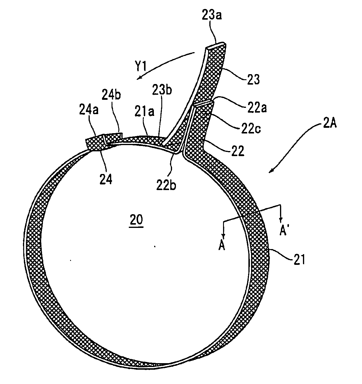
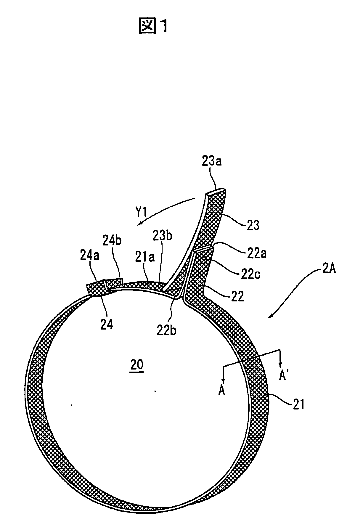
[0061]FIG. 1 shows a boot fixing band 2A, which is a tightening band of the present invention, according to the embodiment. The shape and components of the boot fixing band 2A of the embodiment are the same as those of the known boot fixing band 2 shown in FIG. 7, so the same parts are denoted by the same reference numerals and the corresponding description will be omitted or simplified.

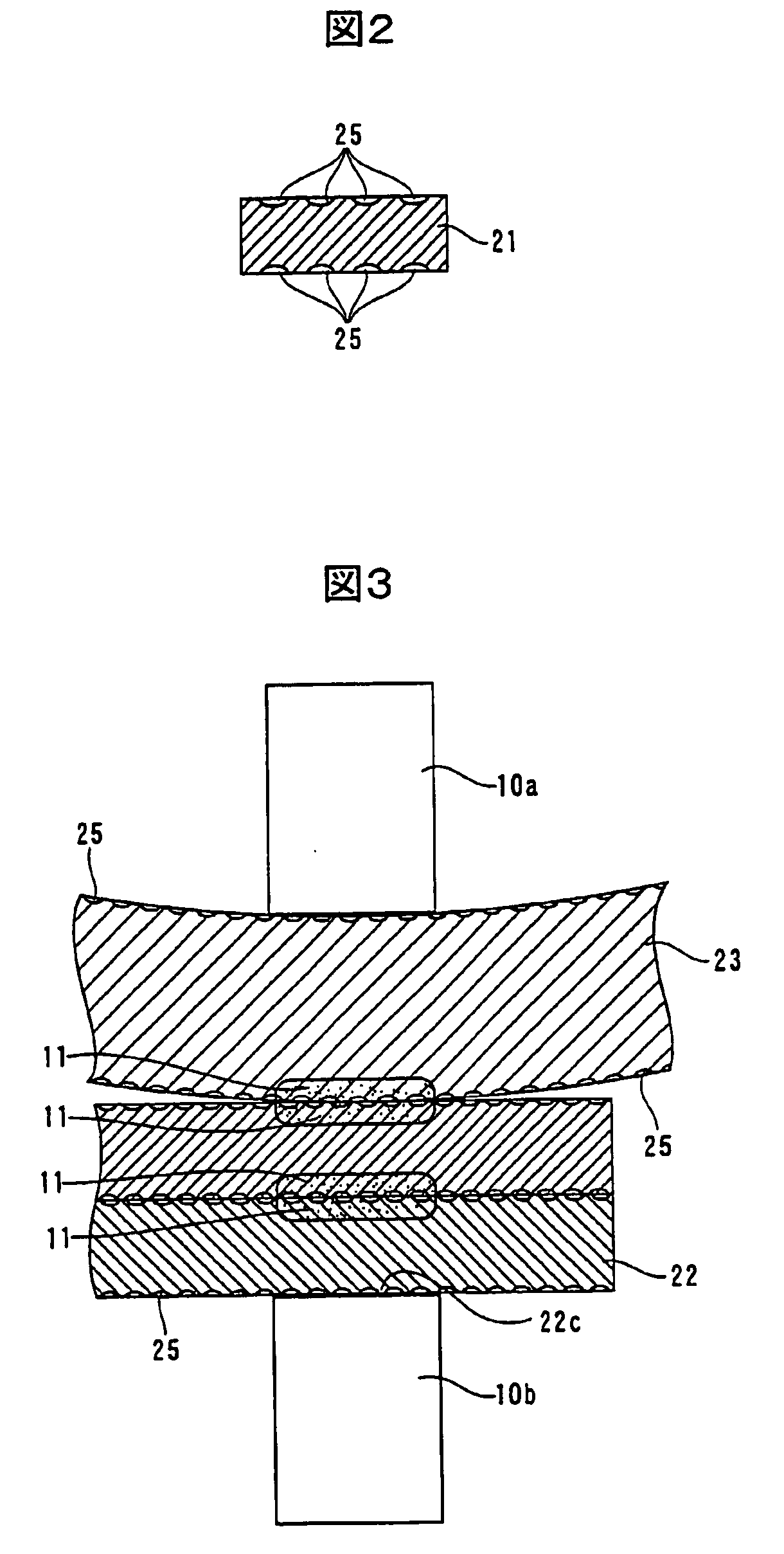
[0062] The boot fixing band 2A of the embodiment is different from the known boot fixing band in that a fine pattern 25 of projections and depressions (see FIG. 2) is formed on the surface (in this embodiment, both front and rear surfaces) of each component: the band main body 20 consisting of the ring portion 21 and the band protrusion 22; the lever plate 23; and the lever-plate fixing member 24.

[0063] The pattern 25 is formed by providing depressions on the surfaces of the band main body 20, the lever plate 23, and the ...


PUM

PropertyMeasurementUnit
Lengthaaaaaaaaaa
Lengthaaaaaaaaaa
Depthaaaaaaaaaa

Abstract

A tightening band used for fixing, for example, a cover for protecting a joint of a rotary shaft of an automobile, and a method for producing the same. The tightening band realizes an improved workability of attachment, a proper tightening strength, a wider applicable range of members to be tightened, and a stable tightening strength lasting for a long time. In the tightening band, a pattern of projections and depressions is formed on the surface of each component. Preferably, the pattern is formed by providing depressions, each having a depth of 2 μm to 30 μm, on the surface of a band main body, a lever plate, and a lever-plate fixing member.

Description

TECHNICAL FIELD [0001] The present invention relates to a tightening band used for fixing, for example, a cover for protecting a joint of a rotary shaft to the joint in an automobile, and a method for producing the same. BACKGROUND ART [0002] A cover for protecting a joint of a rotary shaft of an automobile is generally called a “boot”. The boot is used at many parts, for example, at a joint of a drive shaft for transferring the torque of a differential gear to wheels (the joint between a rotary shaft on the differential gear side and a rotary shaft on the wheel-attached side) and at a joint for transferring the torque of a handle to a wheel steering shaft. In an automobile, boots are provided at no less than 30 parts. [0003] This type of boot typically has a pleated periphery as shown in FIG. 6 and the cross section thereof is circular defining a hollow. In this boot 1, a tightening band for fixing the boot (hereinafter referred to as a “boot fixing band”), which is not shown in FI...

Claims


Application Information

Patent Timeline
IPC IPC(8): F16B2/08B21D31/00F16L3/137F16L3/233
CPCF16L3/137Y10T24/1457F16L3/233
Inventor NAGATA, KENTARO
Owner NAGATA KENTARO
Why Eureka
Try Eureka