Adjustable bolt hole marker

a bolt hole marker and adjustment technology, applied in the field of adjustable bolt hole markers, can solve the problems of separating the base plate or dislodging the bolt from the concrete foundation, the base plate cannot be secured tightly to the foundation, and the hole alignment is not per

Inactive Publication Date: 2005-11-10
PEREA GABRIEL I
View PDF6 Cites 9 Cited by
  • Summary
  • Abstract
  • Description
  • Claims
  • Application Information

AI Technical Summary

Problems solved by technology

The problem with this approach was that the shafts of the bolts extending from the concrete slab were often times not perpendicular, which resulted in improper alignment of the holes to receive the bolts.
Often times this resulted in splitting the base plate or dislodging the bolt from the concrete foundation.
The major problem with this approach was that the base plate could no longer be secured tightly to the foundation, lessening its stability and strength thereby effecting the frame structure erected above the floor.
Unfortunately, recent building codes in some states req...

Method used


Image

  • Adjustable bolt hole marker
  • Adjustable bolt hole marker
  • Adjustable bolt hole marker

Examples


Embodiment Construction

[0012] Unless defined otherwise, all terms used herein have the same meaning as are commonly understood by one of skill in the art to which this invention belongs. All patents, patent applications and publications referred to throughout the disclosure herein are incorporated by reference in their entirety. In the event that there is a plurality of definitions for a term herein, those in this section prevail.

[0013] The term “affixed” as used herein refers to a means for securely retaining one element of the device to another element by a variety of means known to one skilled in the art, such as, for example brazing, welding, soldering or adhesive.

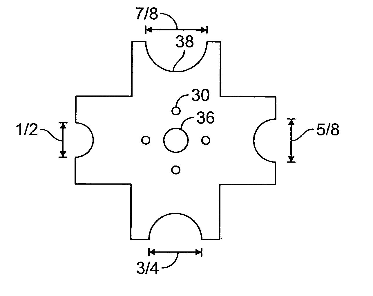
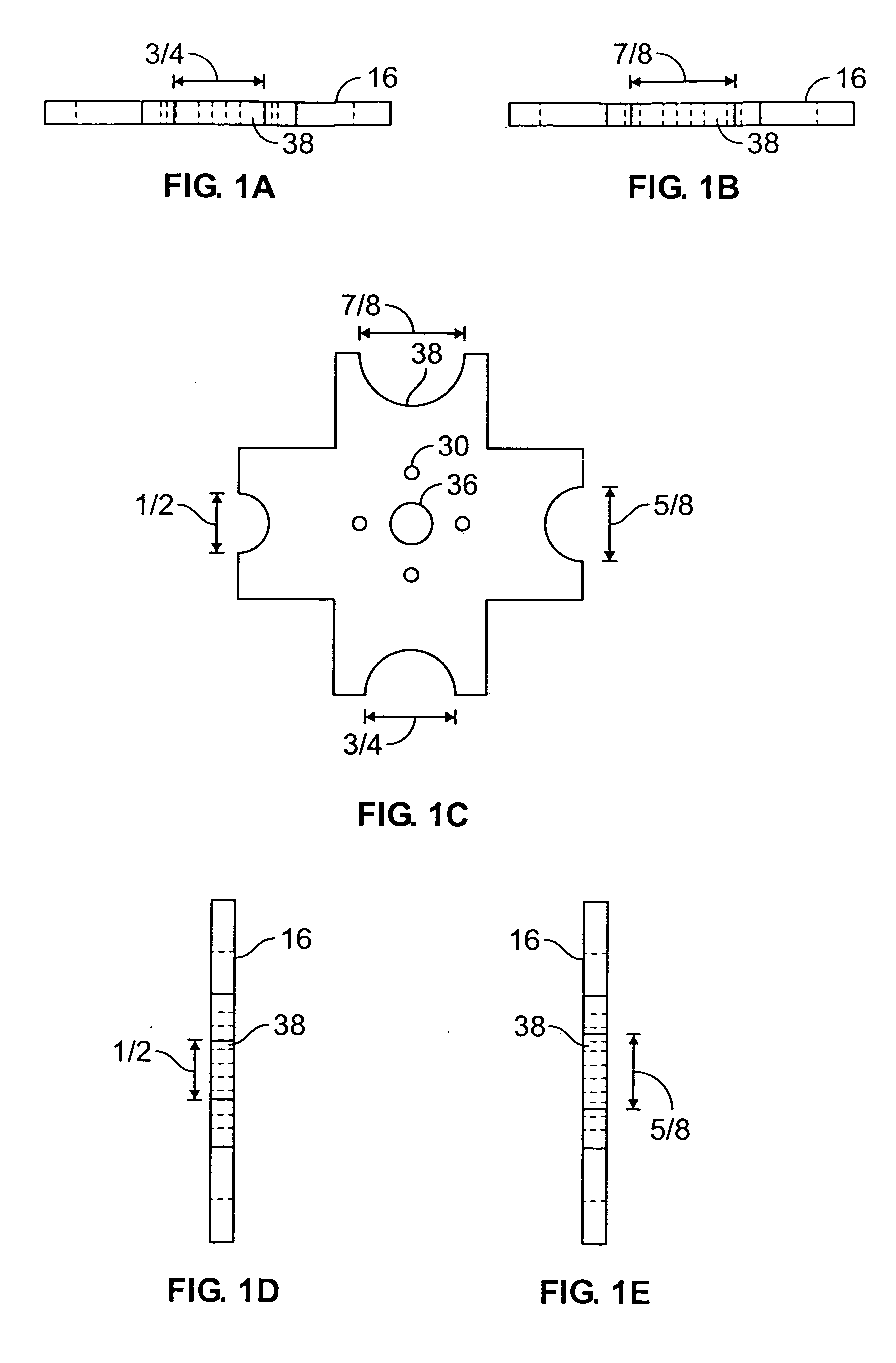
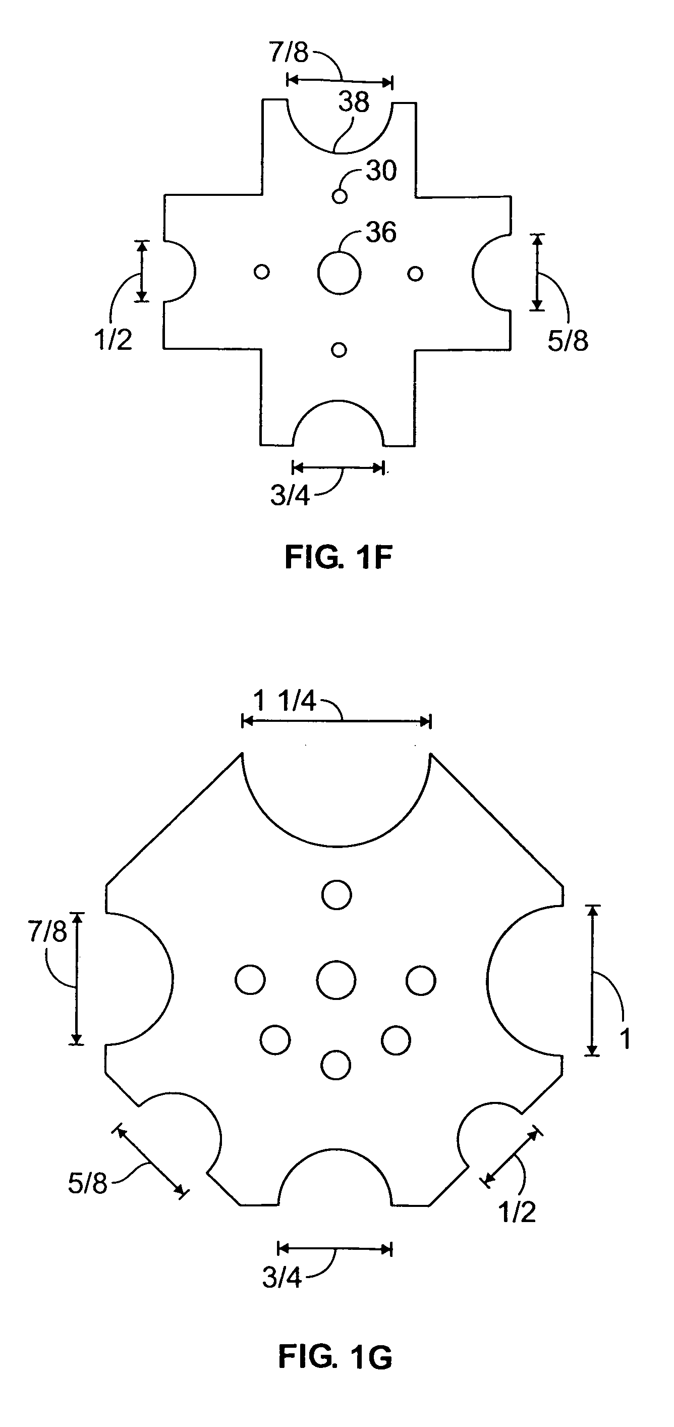
[0014] The present invention contemplates a variety of constructions for the bolt hole marking device. Preferably one contemplated construction comprises a tubular body having a top and a bottom; an elongated base plate having a upper surface, the upper surface having two ends, at least two pegs positioned on the upper surface, one on each...


PUM


Abstract

A bolt hole marking device comprising a tubular body having a top and a bottom, an elongated base plate having a upper surface, a rod fitted within the tubular body having a gripping end and a pointed end and at least two discs rotatably mounted on the base plate one on each end. The upper surface of the base plate having two ends, at least two pegs positioned, one on each end and extending perpendicular to the base plate and at least one aperture at a predetermined distance between the pegs. The bottom of the tubular body is positioned over the aperture and affixed to the base plate. The pointed end of the rod may be extended beyond the bottom of the tubular body. The at least two discs having a plurality of recesses of different radii formed therein arranged about the periphery of the discs and a plurality of apertures able to receive the pegs for fixing the discs in position on the base plate.

Description

REFERENCE TO RELATED APPLICATIONS [0001] This application is a continuation-in-part application of provisional patent application Ser. No. 60 / 567,839 filed 4 Mar. 2004.TECHNICAL FIELD [0002] The present invention relates to building, constructing and fabricating structures, more specifically the present invention is utilized to locate and mark bolt hole positions in framing members to be affixed to bolts set in structural foundations. BACKGROUND OF THE INVENTION [0003] A conventional technique used in construction of residential and commercial building involves concrete foundations made of poured cement with threaded bolts being set upright in the edges of the wet cement for subsequently securing the base plate of the frame structure. Historically the base plate was marked for drilling by placing the base plate over the bolts and impacting the base plate with a hammer to leave the impression of the bolt ends in the base plate. The problem with this approach was that the shafts of th...

Claims


Application Information

Patent Timeline
IPC IPC(8): B25D5/00B25H7/04G01B3/14
CPCB25H7/04B25D5/00
Inventor PEREA, GABRIEL I.
Owner PEREA GABRIEL I
Why Eureka
Try Eureka