Clothes dryer

a clothes dryer and dryer technology, applied in the field of clothes dryers, can solve the problems of deteriorating the dry efficiency of clothes, the inability to stabilize the heat pump mechanism in a safe state, and the inability to discharge the thermal energy necessary for drying clothes, so as to reduce the drying time and save energy

Inactive Publication Date: 2005-11-10
PANASONIC CORP
View PDF11 Cites 62 Cited by
  • Summary
  • Abstract
  • Description
  • Claims
  • Application Information

AI Technical Summary

Benefits of technology

[0006] It is, therefore, an object of the present invention to provide a clothes dryer, which is capable of stabilizing the heat pump mechanism thereof, and achieving a reduction of drying time and a saving of energy.

Problems solved by technology

Accordingly, compressor 75 is rapidly overloaded so that the heat pump mechanism cannot be stabilized in a safe state.
However, this scheme is problematic in that a part of the drying air heated by heat radiator 74 is discharged to outside of the clothes dryer before it is introduced into drying chamber 66 so that thermal energy necessary for drying clothes is uselessly discharged, thereby deteriorating a dry efficiency of clothes.

Method used


Image

  • Clothes dryer
  • Clothes dryer
  • Clothes dryer

Examples


first embodiment

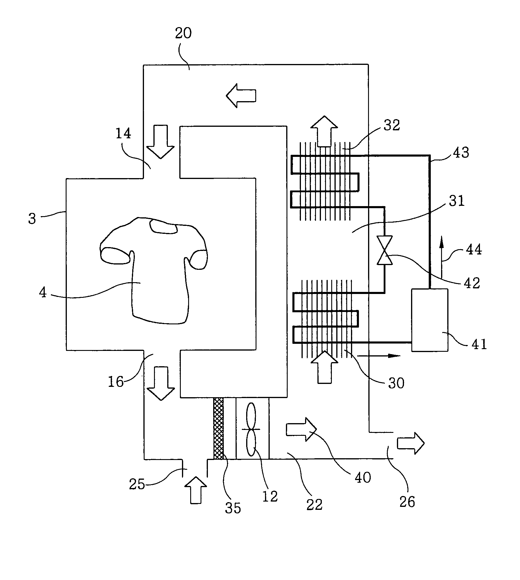
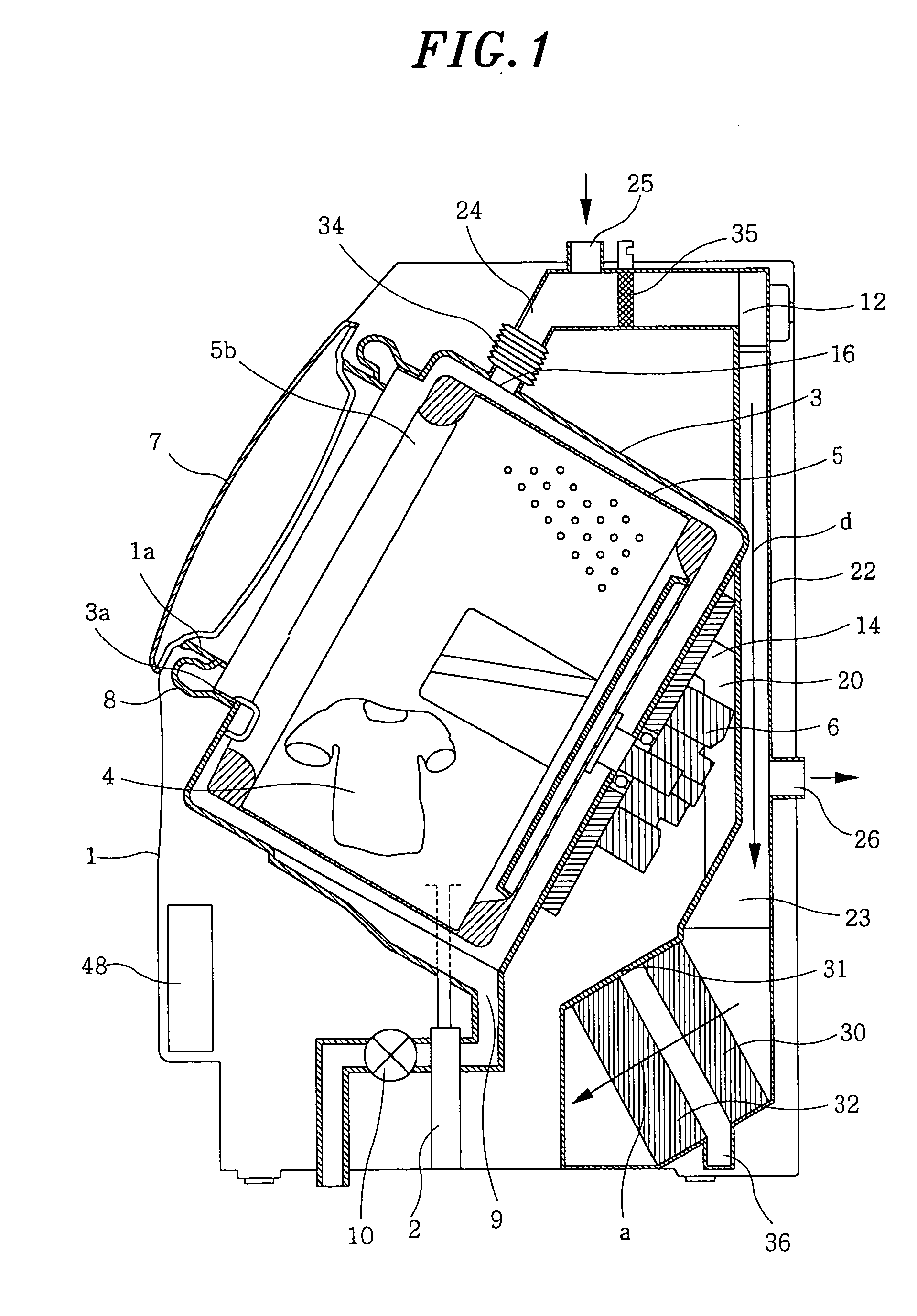
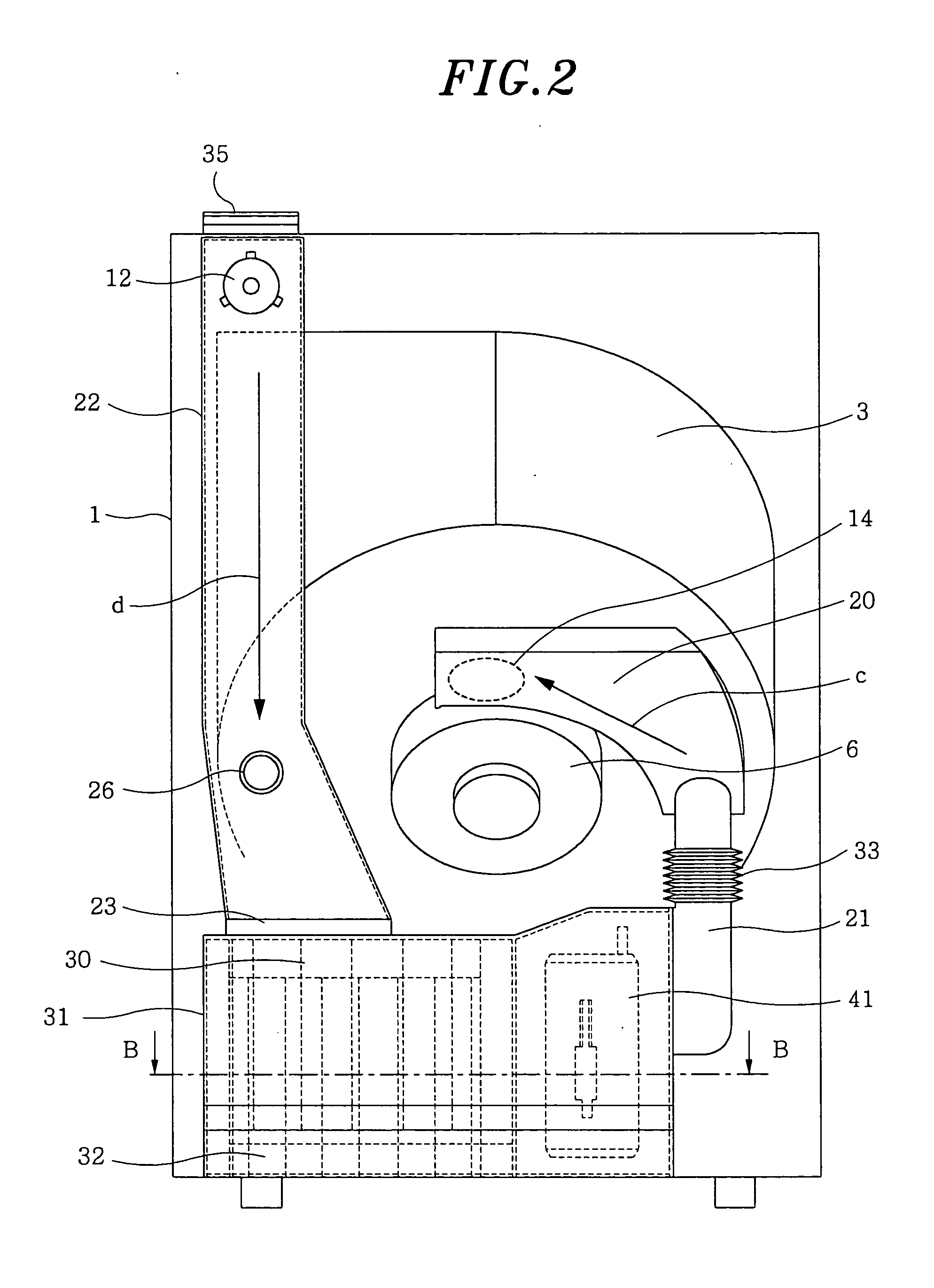
[0024]FIG. 1 is a sectional view of a clothes dryer having a washing function in accordance of a first embodiment of the present invention. FIG. 2 is a rear view of the clothes dryer of FIG. 1. FIG. 3 is a sectional view taken along line B-B of FIG. 2. FIG. 4 is a schematic system diagram showing the construction of a heat pump mechanism and the flow of drying air in accordance with the first embodiment.

[0025] Outer tub 3 is elastically supported by a plurality of suspensions 2 in housing 1. The vibrations generated at the time of washing and dewatering are absorbed by suspensions 2. Cylindrical inner tub 5 accommodating therein clothes 4 is rotatably installed inside outer tub 3, and is rotated by drive motor 6. Outer tub 3 serves as a washing chamber for clothes 4 during a washing process, and as a drying chamber for clothes 4 during a drying process.

[0026] Opening 1a is formed in the front side of housing 1 for loading / unloading clothes 4 into / from inner tub 5. Door 7 is instal...

second embodiment

[0046]FIG. 5 is a sectional view of a clothes dryer having a washing function in accordance with a second embodiment of the present invention. FIG. 6 is a rear view of the clothes dryer shown in FIG. 5. FIG. 7 is a schematic system diagram showing the construction of a heat pump mechanism and the flow of drying air in accordance with the second preferred embodiment of the present invention. FIG. 8 represents graphs showing the outputs of a state detection unit and the control states of a regulating valve in the clothes dryer having a washing function in accordance with the second preferred embodiment. FIG. 9 depicts graphs showing the outputs of the state detection unit and the control states of the regulating valve and a compression capacity varying unit in the clothes dryer having a washing function in accordance with the second preferred embodiment. The elements identical with those of the first embodiment are designated by the same reference numerals, and detailed descriptions t...

third embodiment

[0066]FIG. 10 is a schematic system diagram showing the construction of a heat pump mechanism and the flow of drying air in accordance with a third embodiment of the present invention. The elements identical with those of the first and the second embodiments are designated by the same reference numerals, and detailed descriptions thereof are omitted.

[0067] The embodiment of FIG. 10 is characterized in that state detection unit 45 detects the temperature of coolant. In this embodiment, state detection unit 45 is installed in pipeline 43 passing through heat radiator 32 to detect a temperature of coolant flowing in and along pipeline 43. Control unit 48 controls regulating valve 27 and compression capacity varying unit 46 so that the temperature of the coolant detected by state detection unit 45 falls within a predetermined temperature range. In this way, it is possible to control the amount of heat radiation from air discharge port 26 and compression capacity while monitoring the st...


PUM


Abstract

A clothes dryer includes a drying chamber, a heat pump mechanism, and an air circulation path. The heat pump mechanism includes a compressor, a heat radiator for radiating the heat of compressed coolant, a throttle unit for reducing the pressure of the high-pressure coolant, and a heat absorber for absorbing heat using the low-pressure coolant. An air circulation path circulates drying air from the drying chamber through the heat absorber and the heat radiator back to the drying chamber. The air circulation path is provided with an air discharge port at a position between the drying chamber and the heat absorber so that a part of the drying air flowing through the air circulation path from the drying chamber to the heat absorber is discharged through the air discharge port to outside of the air circulation path.

Description

FIELD OF THE INVENTION [0001] The present invention relates to a clothes dryer for drying clothes and a clothes dryer having a washing function. BACKGROUND OF THE INVENTION [0002] A conventional drum-type clothes dryer is constructed as shown in FIG. 14. The construction of the convention drum-type clothes dryer will be described below. As shown in FIG. 14, rotary drum 63 is installed in outer casing 61 to be rotated about horizontal shaft 62. Opening 64 is formed in the front side of rotary drum 63 to face the front side of outer casing 61, and is selectively opened and closed by door 65. Air circulation path 67, including drying chamber 66 defined in rotary drum 63, is defined in outer casing 61. Air circulation path 67 includes drying chamber 66, air blowing chamber 68 and heat exchanging chamber 69. Air circulation path 67 circulates air in such a way that the air in drying chamber 66 flows into air blowing chamber 68 through air exhaust holes 70 formed in the back side of dryin...

Claims


Application Information

Patent Timeline
Patent Type & Authority Applications(United States)
IPC IPC(8): D06F58/02D06F58/04D06F58/20F25B1/00D06F58/28F25B9/00
CPCD06F58/02F25B2309/061F25B9/008D06F58/206D06F58/48D06F2103/50D06F2105/32D06F2103/32Y02B40/00D06F58/04
Inventor YABUUCHI, HIDETAKANAKAMOTO, SHIGEHARUTAHARA, MIKIO
Owner PANASONIC CORP
Why Eureka
Try Eureka