Relative humidity sensor enclosed with kapton type heater
a technology of relative humidity and sensor, applied in the field of sensor methods and systems, can solve the problems of erroneous readings, dissipation effect, and elements utilized as resistive components, and achieve the effect of reducing the volume of water
- Summary
- Abstract
- Description
- Claims
- Application Information
AI Technical Summary
Benefits of technology
Problems solved by technology
Method used
Image
Examples
first embodiment
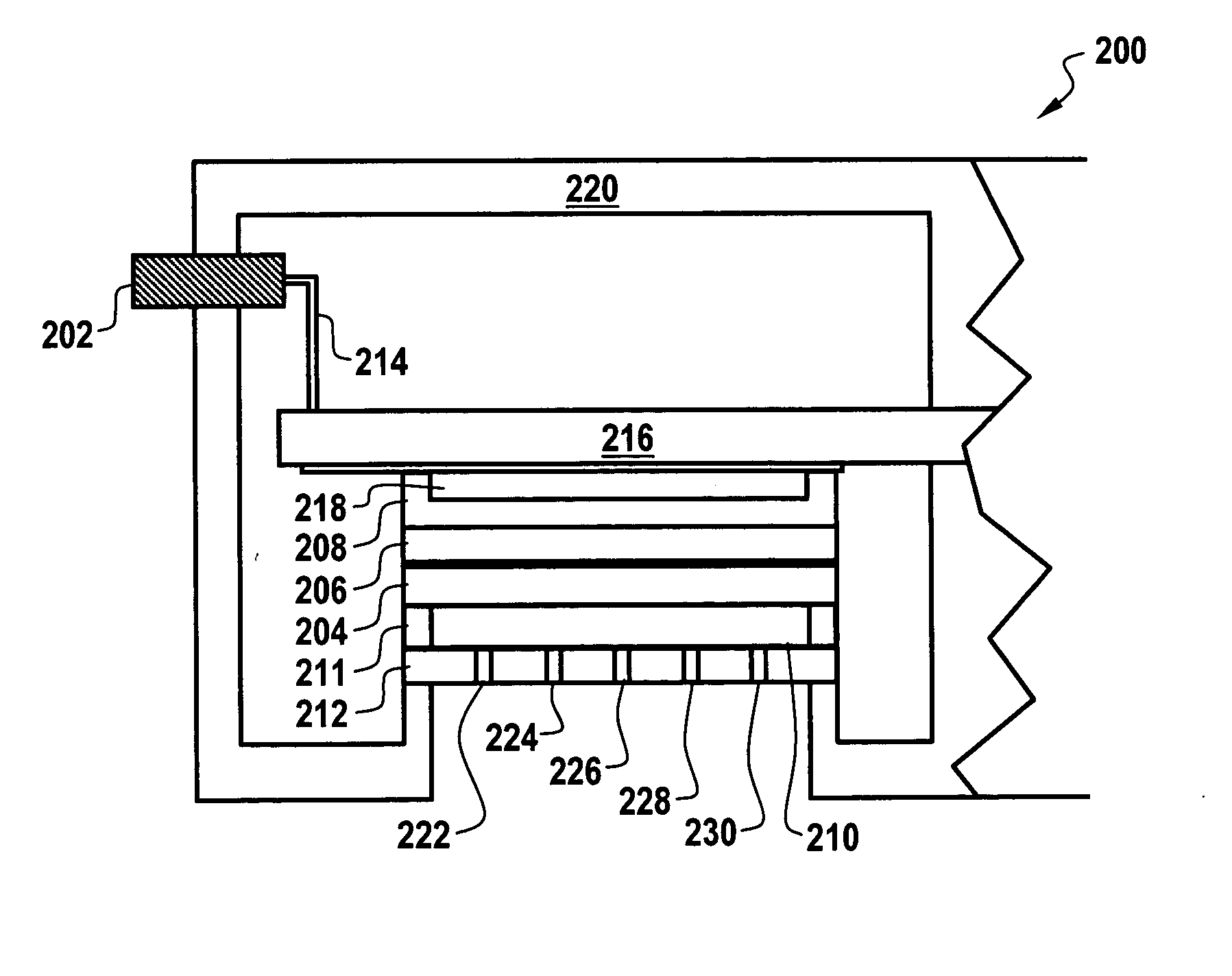
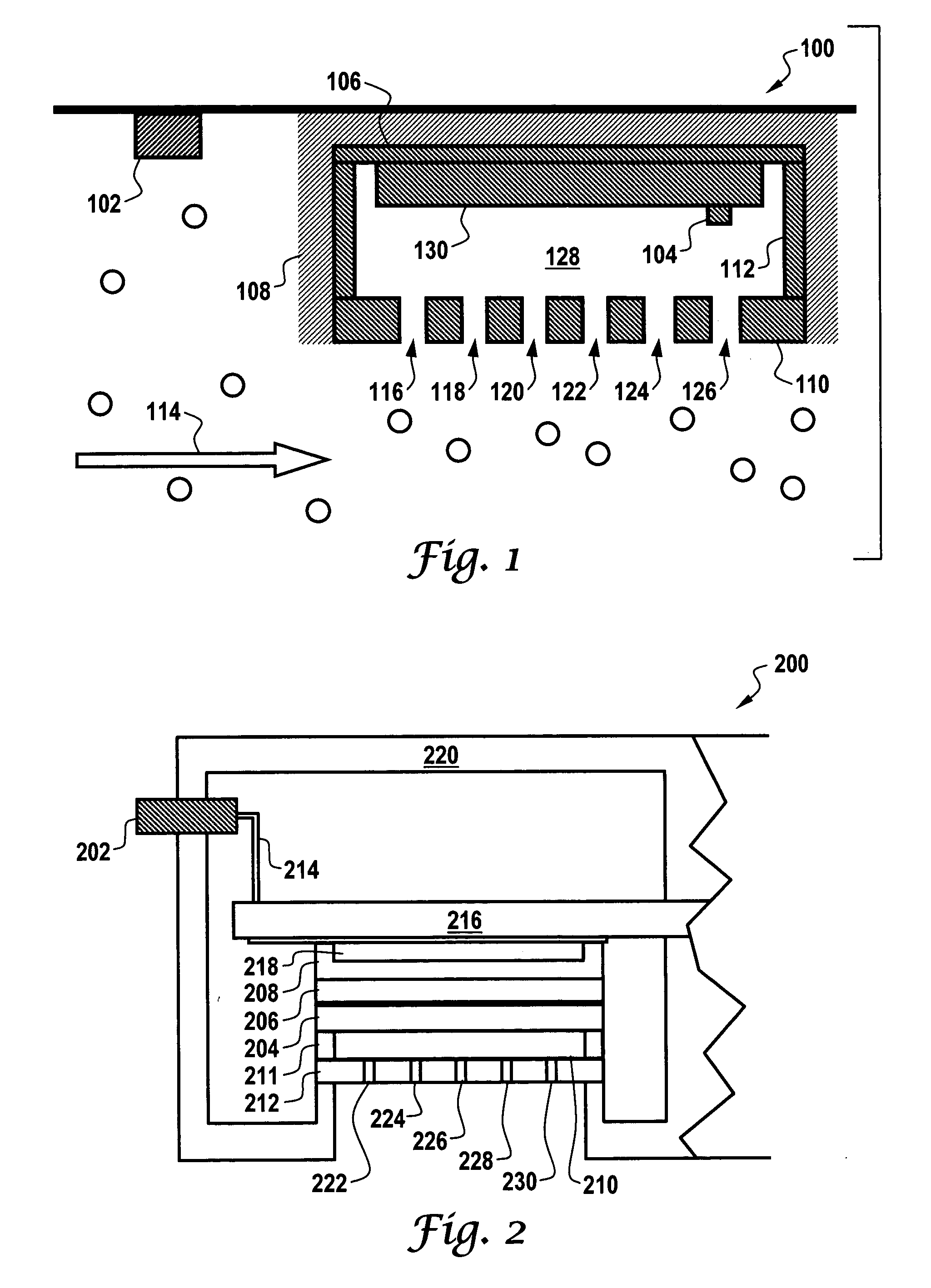
[0058] Based on the foregoing, it can be appreciated that varying sensor systems and methods are disclosed herein. In accordance with a first embodiment, an RH sensor can be associated with one or more heating elements, wherein a perimeter of the RH sensor is surrounded with a relatively conductive material. A thin substrate material can surround and laminate the heating element, such that the heating element is perforated to permit humid air to pass through the heating element and wherein the heating element is assembled slightly offset from a surface of the RH sensor.
[0059] Air that is saturated with two phase flow of water vapor and minute droplets can then pass through and be heated by the heating element in order to evaporate water droplets associated with the water vapor to thereby reduce relative humidity to a measurable level. An additional heating element can be bonded to a base of the RH sensor. The thin substrate material can be configured from a polymide polymer, such as...
second embodiment
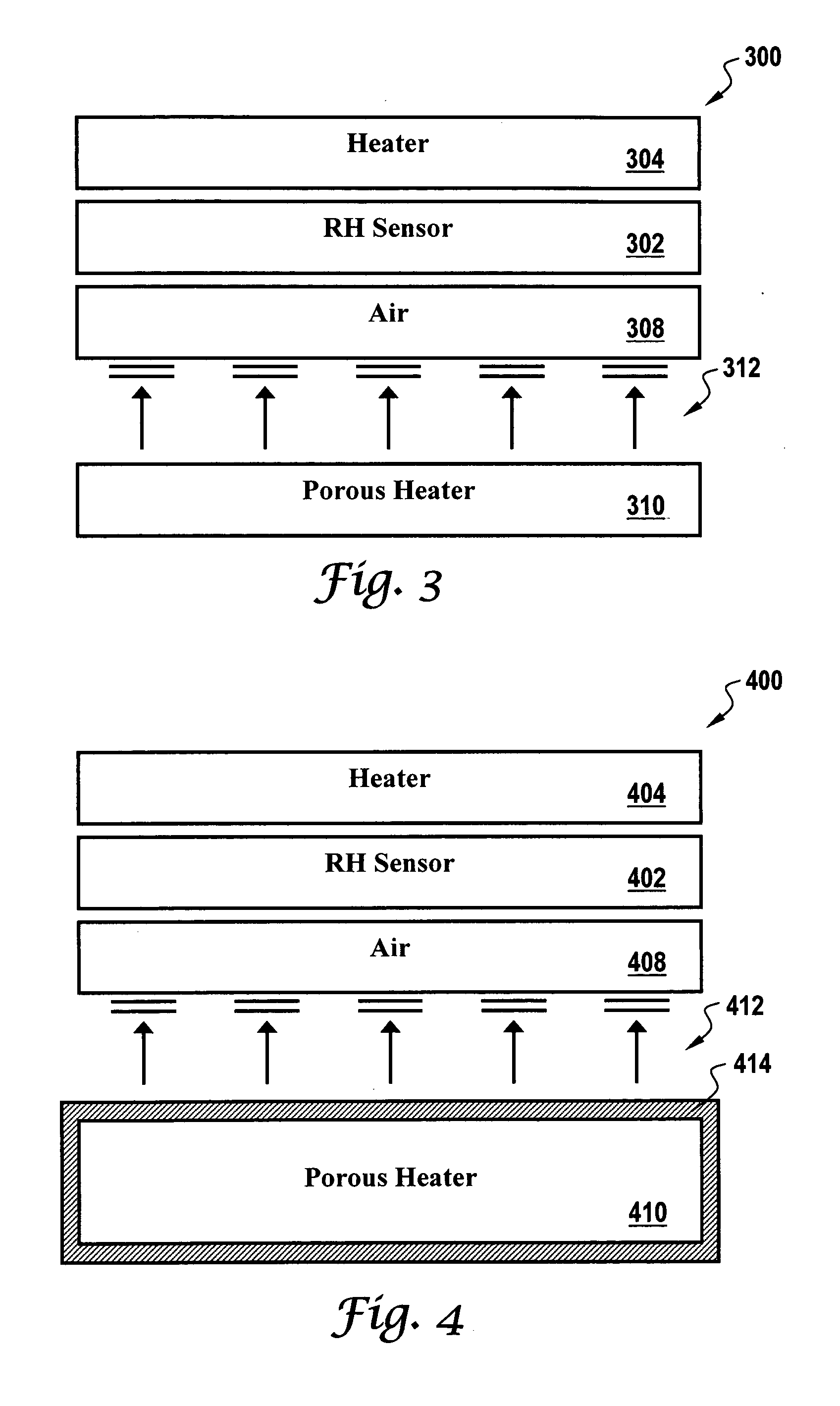
[0060] In accordance with a second embodiment, an RH sensor can be associated with one or more ceramic heating element, wherein a perimeter of the RH sensor is surrounded with a relatively conductive material. A resistive material can surround and laminate the ceramic heating element. The ceramic heating element can be configured from a porous material, wherein air that is saturated with water vapor passes through and is heated by the ceramic heating element in order to evaporate water droplets associated with the water vapor to thereby reduce relative humidity to a measurable level. One or more other heating elements can be bonded to the base of the RH sensor. The porous material forming the ceramic heating element can be formed by providing a plurality of laser drilled holes to create porosity thereof. Additionally, a filter material can be located slightly offset from the RH sensor to create a thin space of stagnant air adjacent to the RH sensor.
third embodiment
[0061] In accordance with a third embodiment, an RH sensor can be associated with one or more heating elements, wherein the RH sensor is surrounded by a sheet of porous resistive material in a woven or perforated pattern or state. The porous heating element can be configured to permit humid air to pass through the porous heating element. The porous heating element can be further assembled slightly offset from a surface of the RH sensor, wherein air that is saturated with water vapor passes through and is heated by the porous heating element in order to evaporate water droplets thereof to thereby reduce relative humidity to a measurable level. Additionally, a flat heating element can be bonded to the base of the RH sensor to conduct heat and insure uniform heating about the RH sensor. The porous resistive material can be formed from material such as tantalum or nichrome. A filter material can also be located slightly offset from the RH sensor to create a thin space of stagnant air ad...
PUM
 Abstract
Description
Claims
Application Information
 - R&D
- Intellectual Property
- Life Sciences
- Materials
- Tech Scout
- Unparalleled Data Quality
- Higher Quality Content
- 60% Fewer Hallucinations
Browse by: Latest US Patents, China's latest patents, Technical Efficacy Thesaurus, Application Domain, Technology Topic, Popular Technical Reports.
© 2025 PatSnap. All rights reserved.Legal|Privacy policy|Modern Slavery Act Transparency Statement|Sitemap|About US| Contact US: help@patsnap.com


