Sputter targets and methods of forming same by rotary axial forging

a technology of rotary axial forging and sputtering target, which is applied in the direction of sputtering coating, vacuum evaporation coating, metal material coating process, etc., can solve the problem of the amount of time to work the material, and achieve the effect of less labor intensive operations and low cos

Active Publication Date: 2005-11-10
GLOBAL ADVANCED METALS USA
View PDF17 Cites 26 Cited by
  • Summary
  • Abstract
  • Description
  • Claims
  • Application Information

AI Technical Summary

Benefits of technology

[0005] A feature of the present invention is to provide a method to produc

Problems solved by technology

Generally, these methods are work intensive in that they take large amounts of time to work the material since these forging or

Method used


Image

  • Sputter targets and methods of forming same by rotary axial forging
  • Sputter targets and methods of forming same by rotary axial forging
  • Sputter targets and methods of forming same by rotary axial forging

Examples


example

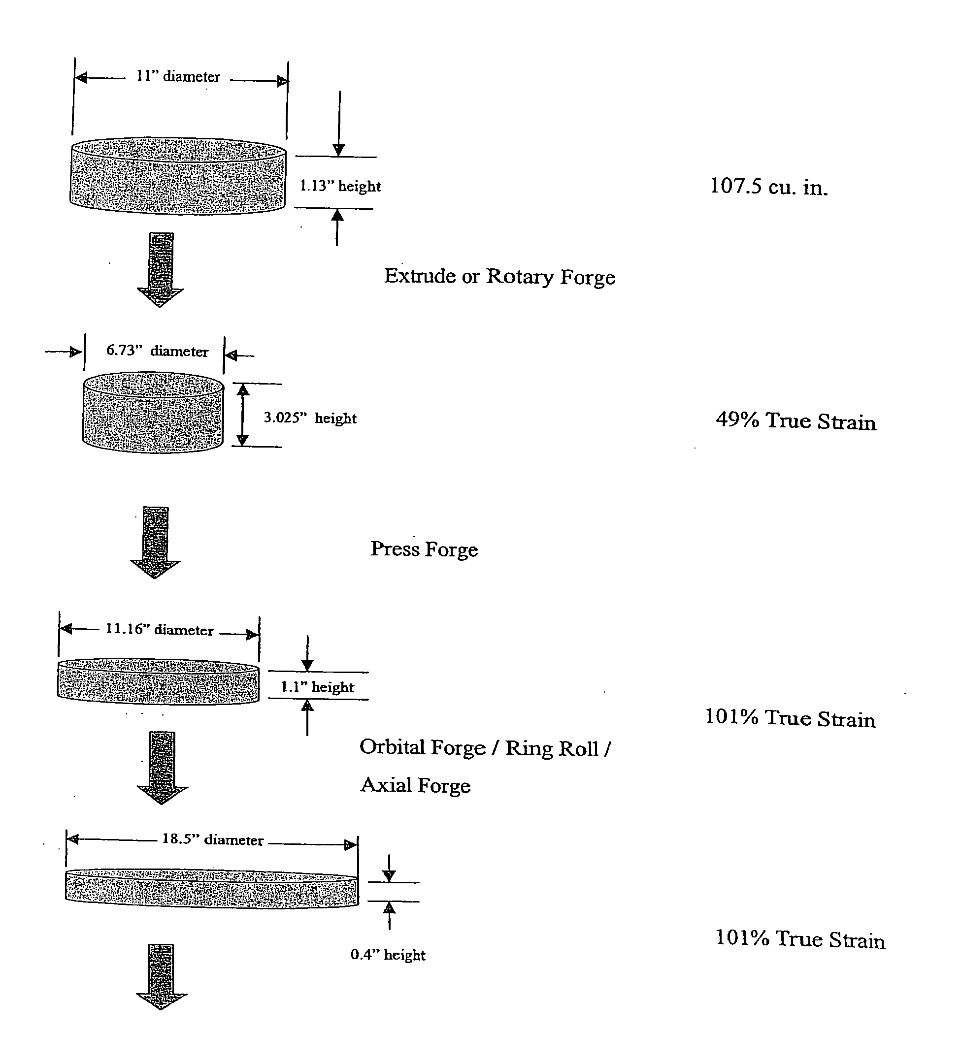
[0058] Table 1 summarizes the experimental conditions used for rotary forging high purity tantalum for use in the manufacture of sputtering targets. The experimental conditions were used to produce tantalum plates of approximately 11 inches in diameter. For commercial sputtering targets, tantalum blanks with 13 to 18 inches in diameter are useful. The calculations of the force required for these larger diameter plates is provided at the bottom of Table 1. In Table 1, Sample 1A, 1B, 2A, and 2B were annealed prior to orbital forging for 1050 deg C in vacuum for 2 hours soak. Samples 1A and 1B were extruded prior to annealing, going from a 11 inch ingot to a 3.54 inch billet and 5.9 inches long. Samples 3A and 3B were also extruded as in 1A, but with no annealing. Samples 2A and 2B were rotary forged going from a 11 inch ingot to a 3.54 inch billet and 5.9 inches long and annealed as discussed after rotary forging. Samples 4A and 4B were also rotary forged but no annealing.

TABLE 1Orb...


PUM

PropertyMeasurementUnit
Grain sizeaaaaaaaaaa

Abstract

A method of making sputter targets using rotary axial forging is described. Other thermomechanical working steps can be used prior to and/or after the forging step. Sputter targets are further described which can have unique grain size and/or crystal structures.

Description

[0001] This application claims the benefit under 35 U.S.C. §119(e) of prior U.S. Provisional Patent Application No. 60 / 568,592 filed May 6, 2004, which is incorporated in its entirety by reference herein.BACKGROUND OF THE INVENTION [0002] The present invention relates to sputter targets and components used for sputtering. More particularly, the present invention relates to methods of forming sputtering targets as well as the sputtering targets resulting from the methods of the present invention. [0003] There are a variety of ways to make sputtering targets from metals which generally involves taking a powder metallurgy product or a ingot-derived product which is generally in the shape of a billet and subsequently working the billet into the shape of the desired sputter target which many times is planar and circular. The means generally used to work a billet into the desired shape are various methods of forging which are rolling, hammer milling, extruding, upset forging, and the like...

Claims


Application Information

Patent Timeline
IPC IPC(8): C22C14/00C22C16/00C22C27/02C22F1/16C22F1/18C23C14/34
CPCC22C5/02C22C5/06C22C9/00C22C14/00C22C16/00C23C14/3414C22C21/00C22C27/00C22F1/16C22F1/18C22C19/07C22C27/02C22F1/08C23C14/34
Inventor MATERA, JOHN P.FORD, ROBERT B.WICKERSHAM, CHARLES E. JR.
Owner GLOBAL ADVANCED METALS USA
Why Eureka
Try Eureka