Method and apparatus for determining the location of core-generated features in an investment casting

Active Publication Date: 2005-11-10
GENERAL ELECTRIC CO
View PDF13 Cites 13 Cited by
  • Summary
  • Abstract
  • Description
  • Claims
  • Application Information

AI Technical Summary

Benefits of technology

[0005] To adequately address the foregoing problems, an independent datum structure / scheme is added to the core. This additional (secondary) datum structure is arranged so as to be convenient for access and checking by conventional modern gauging equipment such as a Coordinate Measuring Machine (CMM). Known conventional casting / manufacturing approaches typically employ only a single fixed exterior-based primary datum structure for locating and / or holding a turbine airfoil or nozzle part during gauging and machining of the core-produced internal features. Since the core design is free floating, an internal structural feature may ultimately be moved / shifted within the profile limits of the casting and casting process. Consequently, a second set of datums integral to the core is used to provide a reference system specific to the core-produced internal cast features. This core-based reference system provides a means to ensure proper orientation and registration of the core geometry and enables accurate gauging and precision machining of the complex internal structural features that may be a part of a particular airfoil or nozzle design.
[0006] One aspect of the invention is the establishment of a secondary datum scheme integral to the core which identifies the location of core-produced geometry (e.g., internal structural features of a hollow investment-cast article) exclusive of the external investment shell and / or other wax-produced features. The use of an independent core-based datum system allows for correction or compensation of positional variations between the external casting shell and the core. It also allows design changes such as a shift in the core geometry positional location to obtain a “best fit” of the core to the external airfoil shape while achieving a particular desired throat area. Another aspect is to provide an arrangement of core-produced datum pads on internal portions of a hollow investment-cast turbine part that are easily accessible by conventional gauging equipment and are easily removed by machining. A further aspect is to provide an arrangement for producing a hollow investment cast article (e.g., a turbine airfoil, blade or nozzle) that eliminates or at least minimizes the potential of incurring machining / gauging errors due to positional variations of core-produced features and allows precision machining to be performed on core-produced features relative to any core shift which may occur during casting or which may need to be implemented as a result of design changes / modifications.

Problems solved by technology

However, the use of a free-floating core design causes problems during subsequent production machining of the part.
Such variation is highly undesirable when attempting to perform accurate gauging or precision machining operations on these core-produced internal features.
Because of this, automated machining of internal core-produced features is often inaccurate, if not unfeasible.
This is due, at least in part, to the fact that conventional automated machining methods rely upon a part's fixed external datum scheme / structure for locating and / or holding a part during machining / gauging operations and this fixed “primary” datum scheme is inaccurate with respect to internal core-produced cast features due to positional variations of the features caused by the use of a free-floating core.
If these internal core produced features, which have moved relative to the external features during the casting process, were machined based on fixtureing to the external features, the machining tolerances would be excessive.

Method used


Image

  • Method and apparatus for determining the location of core-generated features in an investment casting
  • Method and apparatus for determining the location of core-generated features in an investment casting
  • Method and apparatus for determining the location of core-generated features in an investment casting

Examples


Embodiment Construction

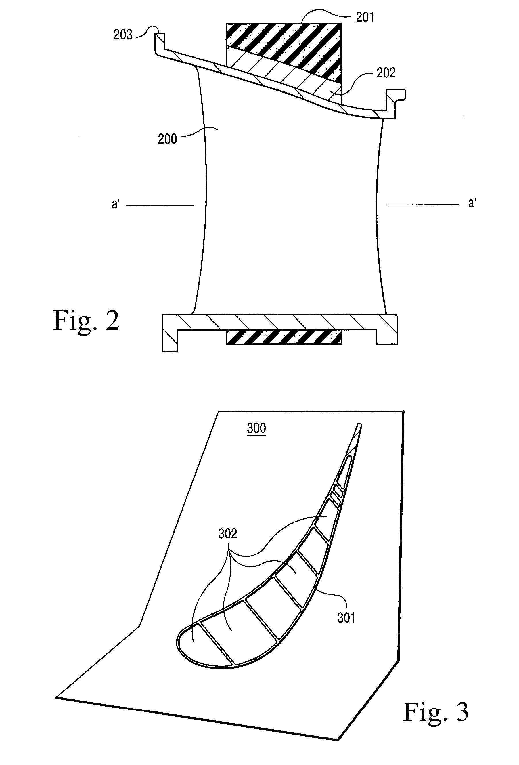
[0013] In the following description specific details are set forth for purposes of explanation only, and not limitation, with respect to a free-floating ceramic core for use in casting a gas turbine engine part where the core forms a cooling passage in the cast article when the core is removed. The present invention is not limited to the specific example illustrated herein and may be practiced with respect to other investment casting cores to make a variety of castings for other applications from a variety of metals and alloys. It will be apparent to one skilled in the art that the non-limiting example discussed herein below may be practiced in other embodiments that depart from these specific details.

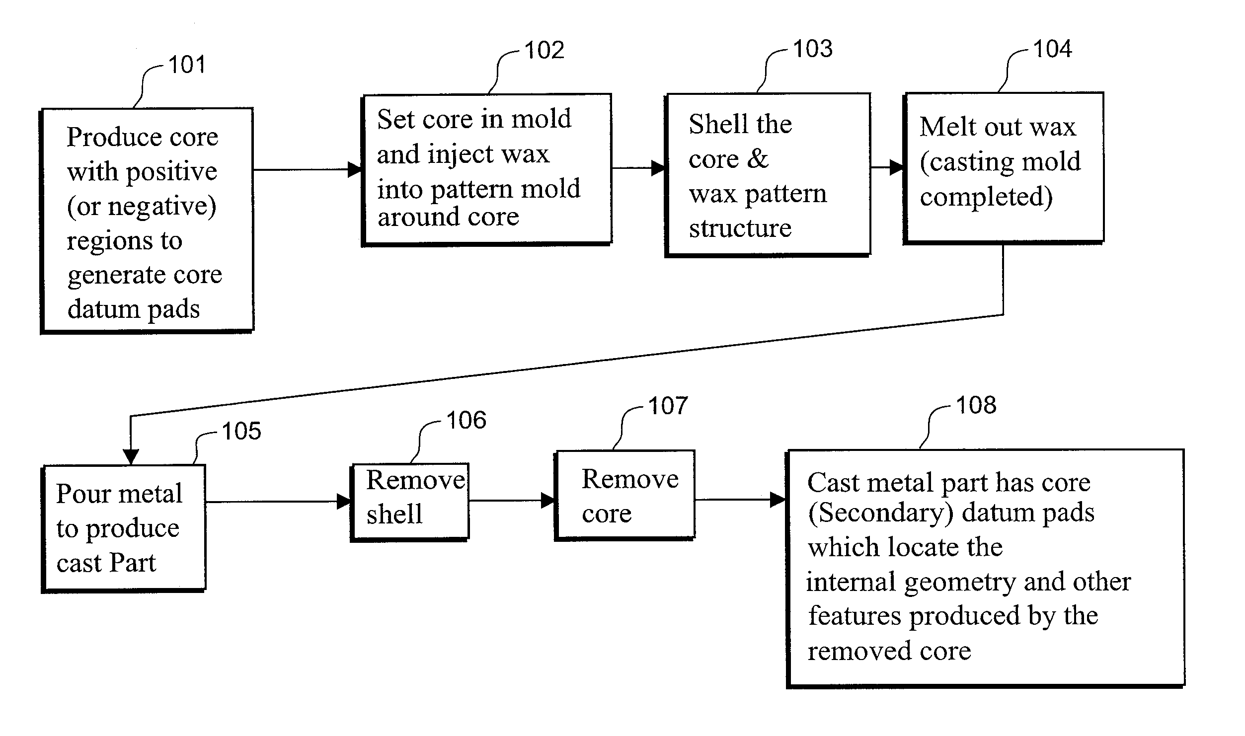
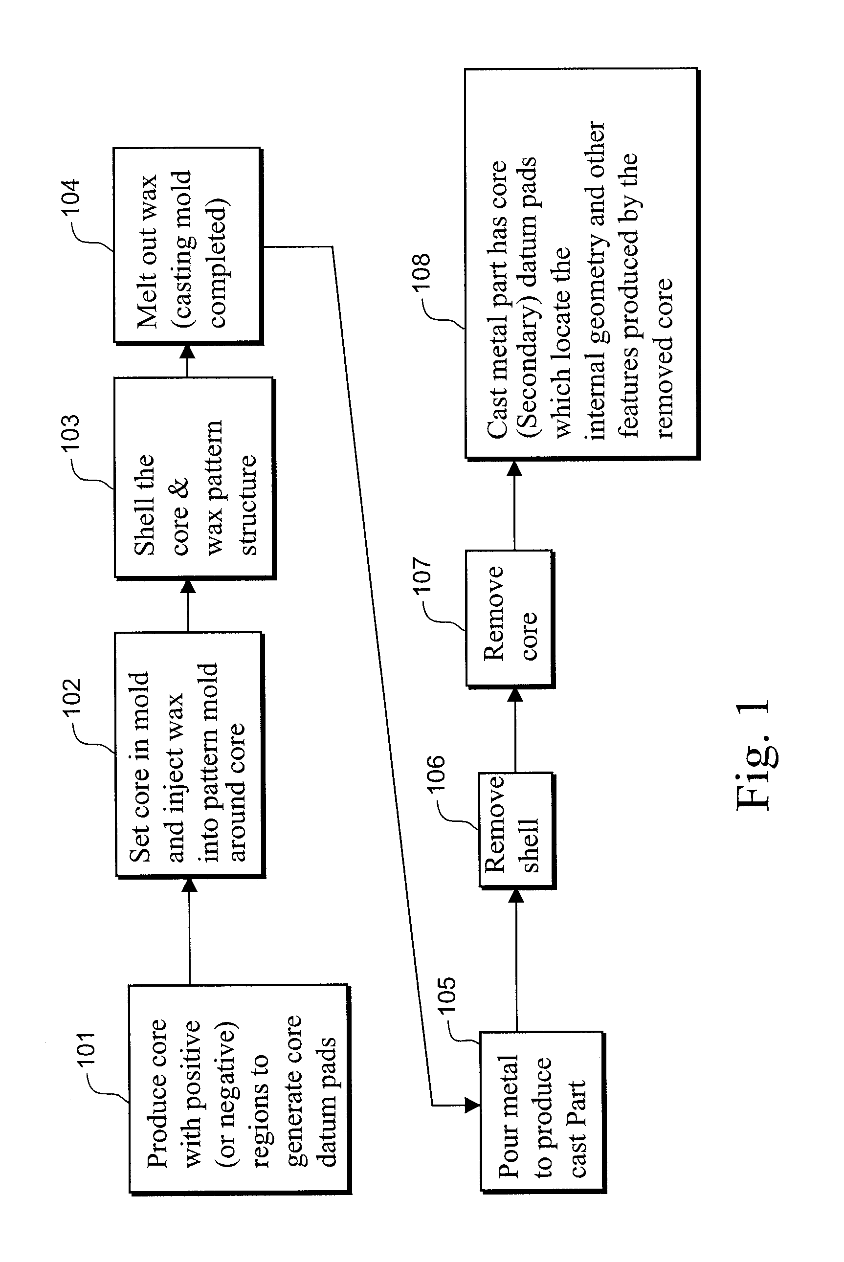
[0014] Illustrated in FIG. 1, is an example process flow diagram for investment casting a hollow metal article, such as a turbine airfoil, having a core-based datum reference system for establishing the position of internal core-produced geometry for subsequent gauging or machining op...


PUM


Abstract

A secondary datum scheme is used for identifying the location of the core-produced internal geometry of hollow investment cast metal parts that are made using a free-floating core design for implementing complex internal structural features. A set of datum pads are cast on a removable portion of the core print out to provide the secondary reference system. This secondary reference system precisely establishes the location of the core-produced internal geometry of the part exclusive of any fixed external primary datum structure / system so that, for example, precision machining and gauging may be performed upon such internal features during subsequent fabrication steps.

Description

BACKGROUND OF INVENTION [0001] Many manufacturers of gas turbine engines are now using advanced investment casting techniques for producing cast metal turbine nozzles or airfoils (e.g., for gas turbine engine blades or vanes) that include intricate air cooling channels to improve efficiency of airfoil cooling. The internal cooling passages are formed in the cast airfoils using one or more complex airfoil shaped ceramic cores positioned in a ceramic shell mold where molten metal is cast in the mold about the core. The ceramic core(s) are responsible for producing internal structural features of the airfoil such as internal cavities and ribs. [0002] A typical ceramic core is made using a plasticized ceramic compound which is injection molded or transfer molded at an elevated temperature in a core die or mold. The core is then hardened by firing or baking. The finished fired core is then positioned within a pattern die cavity in which a fugitive pattern material (e.g., wax or plastic) ...

Claims


Application Information

Patent Timeline
IPC IPC(8): B22C9/04B22C9/10B22C9/24B22D25/02B22D33/04
CPCB22C9/10
Inventor DEVINE, ROBERT H. IIITZEL, GARY M.
Owner GENERAL ELECTRIC CO
Why Eureka
Try Eureka