Self winding electric cord

a self-winding, electric cord technology, applied in the direction of insulated conductors, extensible conductor cables, cables, etc., can solve the problem of negated spring steel biased coiling tendency to re-coil prematurely, and achieve the effect of simple design and economical manufactur

Inactive Publication Date: 2005-11-10
SCHULZ STEVEN MARK
View PDF10 Cites 20 Cited by
  • Summary
  • Abstract
  • Description
  • Claims
  • Application Information

AI Technical Summary

Benefits of technology

[0010] The present invention relates to a novel design for a self-winding electric cord. The novel design of the cord eliminates the need for separate reels to wind the cord. What is provided is an apparatus that transmits electric current as the need arises by unrolling the cord to its expanded length, then it simply rewinds to a compact state when not in use. The apparatus generally comprises of self rolling spring strips encased in insulation and a pair of fastening means fixedly attached to the inside and outside surfaces of the strip such that when the cord is in the coiled position, the fastening means prevents the cord from unwinding. The cord with the spring steel enclosed are biased to a coiled position and when uncoiling the cord is to be folded along its long axis in a predetermined flex joint acting as a hinge. Once manually flexed along this hinged axis the cord remains in a straightened configuration until re-flattened for coiled storage.
[0011] In operation the cord is initially in a coiled stored condition, the apparatus is then manually opened and creased along its long axis, this folding action negates the biased coiling tendency of the spring steel to re-coil prematurely. Once the cord is extended to its full length in this folded condition the cord remains in this stable state for the duration of use. While in operation the extended cord is substantially uncoiled and able to be manipulated to traverse any open space enabling power to be transmitted to remote locations. Once the Electric cord is no longer needed the cord is unflexed at the linear hinge; in other words it is flattened, allowing the natural spring bias to help it re-coil. An additional help in keeping the cord in a neatly wound coil is the hinged center of the cord, it protrudes slightly on its bottom side when the cord is in its flat configuration, it also is slightly recessed on the top side, allowing the cord to mate with itself when coiled. The addition of fastening means creates a secure method of keeping the coil in position when stored in a coiled position.
[0012] In view of the above, it is an object of the present invention to provide an apparatus that can extend to provide power when needed and be simply recoiled for storage without the problems associated with normally twisted round cords.
[0013] It is a further object of the present invention to provide such an apparatus for the compact storage of electric cords and ease of recoiling which is simple in design and economical to manufacture.

Problems solved by technology

In operation the cord is initially in a coiled stored condition, the apparatus is then manually opened and creased along its long axis, this folding action negates the biased coiling tendency of the spring steel to re-coil prematurely.

Method used


Image

  • Self winding electric cord
  • Self winding electric cord
  • Self winding electric cord

Examples


Embodiment Construction

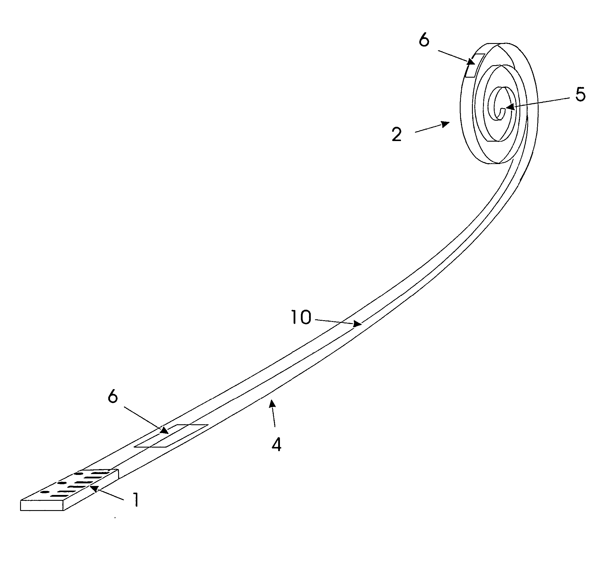
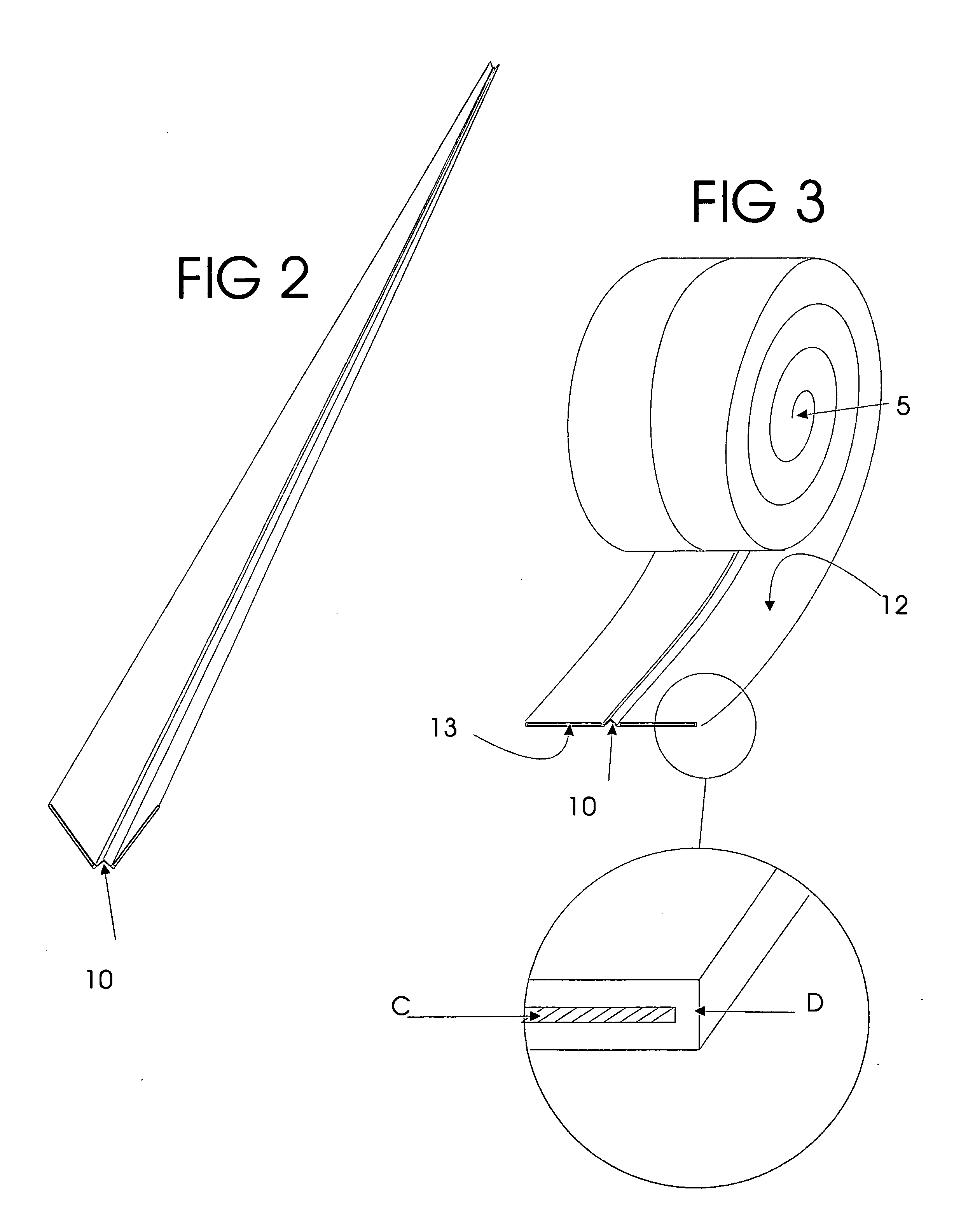
[0020] Referring now to the drawing and in particular FIGS. 1-3, The apparatus of the present invention is designated generally by the numeral 4. Apparatus 4 is generally comprised of self-rolling spring strips C, enclosed by insulation layer D, with fastening means 6, which are fixedly attached to strip 11.

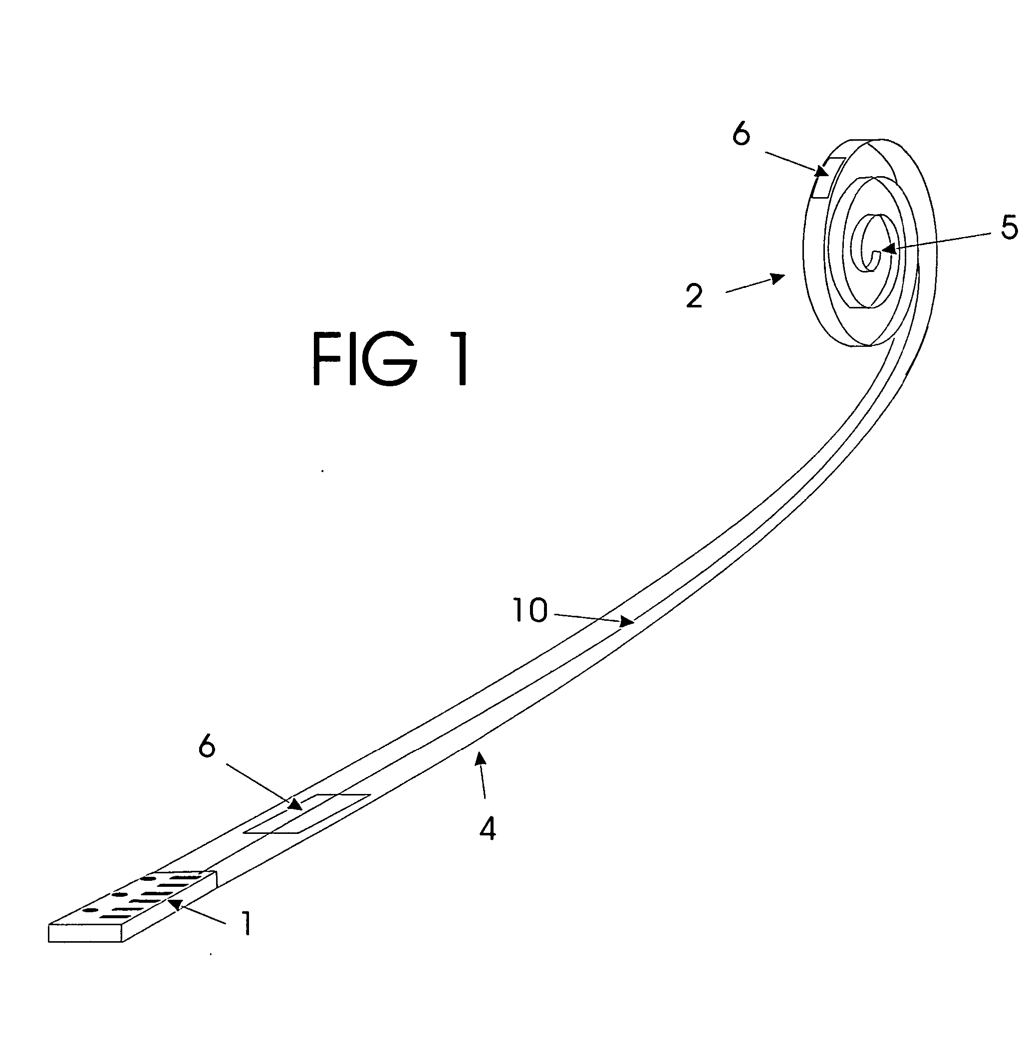
[0021] Spring strip C, is known in the art and is commonly used in steel roll tape measures. Spring strip C has a bias to remain in a coiled state, the coiled steel is sheathed in an insulating layer D. The sheathing is extruded in a segmented shape with a hinged segment 10. Said strip is in a substantially rectangular shape and preferably elongated, as best seen in FIG. 2.

[0022] Fastening means 6, are preferably hook and loop type fasteners such as “VELCRO”. Fastening means 6 is preferably hook type fasteners fixedly attached to surface D, as seen in FIGS. 1 and 3. Fastening means 6 are substantially rectangular in shape and positioned along the length in such a manor as to ma...


PUM

PropertyMeasurementUnit
electric currentaaaaaaaaaa
common electricaaaaaaaaaa
forceaaaaaaaaaa

Abstract

An electric cord utilizing flat strip metal under tension to simplify rewinding the cord. The apparatus comprises a spring biased metal clad within a non-conducting sheath. The spring-loaded metal is biased to effect a concave surface in the general axis congruent to the extreme or long axis. The preloaded spring metal coils in its natural state. The embodiment of the invention locates multiple strips of spring metal in a parallel configuration. The apparatus confines the linear metal strips within a plastic or alternate non-conductor sheath configured to bend or distort the apparatus parallel to the long axis. The apparatus can then be distorted along the major axis to counteract the spring tension delaying the natural coiling of the electric cord. In a basic embodiment the distortion is applied by folding the electric cord along the major axis producing a ridged configuration and resisting the spring from coiling. Reversing the distortion by unfolding the electric cord recreates the spring tension and promotes the self-coiling action.

Description

REFERENCES CITED [0001]3410023November 1968Anello3966121June 1976Littman239 / 1974153189May 1979Hughes294 / 1434262385April 1981Norman294 / 1494402542September 1983Kreutzer294 / 1564582257April 1986Siegler239 / 1974706914November 1987Ground 24 / 4474724548February 1988London 63 / 114796936January 1989Sherin294 / 1485176452January 1993Stern446 / 4865607107March 1997Grieve239 / 1955738398May 1996Miano294 / L15971612October 1999McAuslan383 / 43BACKROUND OF INVENTION [0002] 1. Field of the Invention [0003] The present invention relates to an electric cord designed to be self winding and self storing. The effective coiling and wrapping of such flexible electric cords is desirable from both appearance and safety standpoints. Tangled cords pose a hazard in any workplace as well as an inconvenience in sorting and storing said devices. A need is realized for the development of a simple method of uncoiling the extension cord and the subsequent recoiling of the extension cord. The ease of storage is desirable to prev...

Claims


Application Information

Patent Timeline
Patent Type & Authority Applications(United States)
IPC IPC(8): H01B7/06H01B7/29
CPCH01B7/06
Inventor SCHULZ, STEVEN MARK
Owner SCHULZ STEVEN MARK
Why Eureka
Try Eureka