Wiring base board, method of producing thereof, and electronic device
a wiring base board and multi-layer technology, applied in the direction of printed circuit manufacturing, printed circuit aspects, printed element electric connection formation, etc., to achieve the effects of enhancing the reliability of signal transmission, enhancing the multi-layer structure of via hole parts, and strengthening the stability against external nois
- Summary
- Abstract
- Description
- Claims
- Application Information
AI Technical Summary
Benefits of technology
Problems solved by technology
Method used
Image
Examples
first embodiment
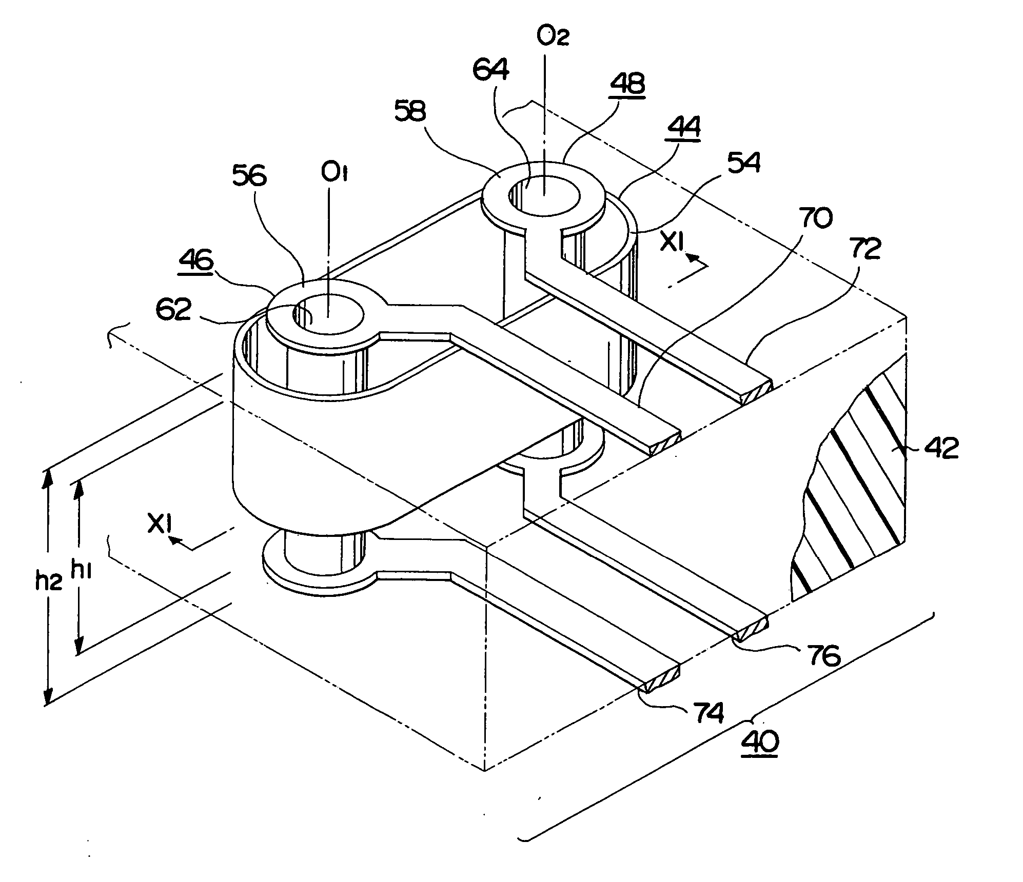
[0057] The first embodiment of the present invention is explained by referring to FIG. 10 and FIG. 11. FIG. 10 is a perspective view showing a differential wiring structure of a wiring base board according to the first embodiment, and FIG. 11 is a sectional view taken along line XI-XI of FIG. 10.
[0058] This embodiment constitutes a wiring base board, which can perform various transmission such as differential transmission of plural signals, by means of multiplexing or double structure of a via hole part. This wiring base board makes it possible to electromagnetically couple between parallel conductors, and, for example, constitutes a double via structure of two cores by giving a structure in which those circumferences are surrounded with a conductor wall.
[0059] For this wiring base board 40, a substrate 42 is used as a core substrate formed by an insulating material. In this substrate 42, the first via hole part 44 is formed, and a plurality of the second via hole parts 46 and 48 ...
second embodiment
[0063] The second embodiment of the present invention is explained by referring to FIG. 12 through FIG. 14. FIG. 12 is a plan view showing a part of a surface of a wiring base board according to the second embodiment, FIG. 13 is a sectional view taken along line XIII-XIII of FIG. 12, and FIG. 14 is a sectional view taken along line XIV-XIV of FIG. 13. In each of the drawings, the same portions as those of the first embodiment are indicated by the same reference numerals.
[0064] A wiring base board 40 of this embodiment shows a specific example of the first embodiment. For example, a conductor wall like an elliptic cylinder is arranged inside the wiring base board 40, and parallel conductors of plural cores are provided at an inside of the conductor wall. By a structure like this, electromagnetic coupling between the parallel conductors is given, and a plural-cored coaxial structure is also constituted.
[0065] As shown in FIG. 12, in this wiring base board 40, the first via hole part...
third embodiment
[0068] The third embodiment of the present invention is explained by referring to FIG. 15 and FIG. 16. FIG. 15 is sectional views showing an example of a producing method of a wiring base board according to the third embodiment, and FIG. 16 is plan views showing a drilling process.
[0069] This embodiment provides a forming method of a wiring base board 40 which has the first and the second via hole parts 44, 46 and 48 forming coaxial structures of plural cores, and so on.
[0070] For production of this wiring base board 40, a substrate 43 formed by an insulating material is used. As shown in FIG. 15A, on a surface and a back face of this substrate 43, wiring patterns 80 and 82 composed of a conductor layer are formed. A reference axis Or is set through positioning of the substrate 43, and, along with this, central axes O1 and O2 to form the via hole parts 44, 46 and 48 are set. Each of the central axes O1 and O2 is set by using the reference axis Or as a standard, and becomes a cente...
PUM
| Property | Measurement | Unit |
|---|---|---|
| Thickness | aaaaa | aaaaa |
| Electrical conductor | aaaaa | aaaaa |
Abstract
Description
Claims
Application Information
 - R&D
- Intellectual Property
- Life Sciences
- Materials
- Tech Scout
- Unparalleled Data Quality
- Higher Quality Content
- 60% Fewer Hallucinations
Browse by: Latest US Patents, China's latest patents, Technical Efficacy Thesaurus, Application Domain, Technology Topic, Popular Technical Reports.
© 2025 PatSnap. All rights reserved.Legal|Privacy policy|Modern Slavery Act Transparency Statement|Sitemap|About US| Contact US: help@patsnap.com


