In-wheel motor system

a technology of in-wheel motors and motor components, which is applied in the direction of propulsion parts, electric propulsion mounting, transportation and packaging, etc., can solve the problems of increasing the unsprung mass, increasing the road holding capacity, and increasing the variation of the ground-contact load of the tir

Active Publication Date: 2005-11-10
BRIDGESTONE CORP
View PDF6 Cites 50 Cited by
  • Summary
  • Abstract
  • Description
  • Claims
  • Application Information

AI Technical Summary

Benefits of technology

[0012] the motor is mounted to the unsprung portion of the vehicle by a damping member comprising a plurality of shock absorbers, each having a spring element and a damper element connected to the spring element in parallel or a damping member comprising either one or more of at least one damper with a spring element, each comprising a spring element and a damper element connected to the spring element in series and at least one composite connection damper whose spring element and damper element connected in parallel are connected to a spring element in series.

Problems solved by technology

In general, in a vehicle having a suspension mechanism such as a spring around its legs, it is known that as the mass of unsprung parts such as a wheel, knuckle and suspension arm so called “unsprung mass” increases, variations in the ground-contact load of a tire become larger and the road holding properties become worse when the vehicle runs on a rough road.
In the in-wheel motor of the prior art, as the motor portion is fixed to the spindle shaft connected to a part called “upright” or “knuckle” which is a frame dress-up part of the vehicle as described above, the above unsprung mass increases by the mass of the in-wheel motor with the result that variations in the ground-contact force of each tire become larger and the road holding properties become worse.

Method used


Image

  • In-wheel motor system
  • In-wheel motor system
  • In-wheel motor system

Examples


embodiment 1

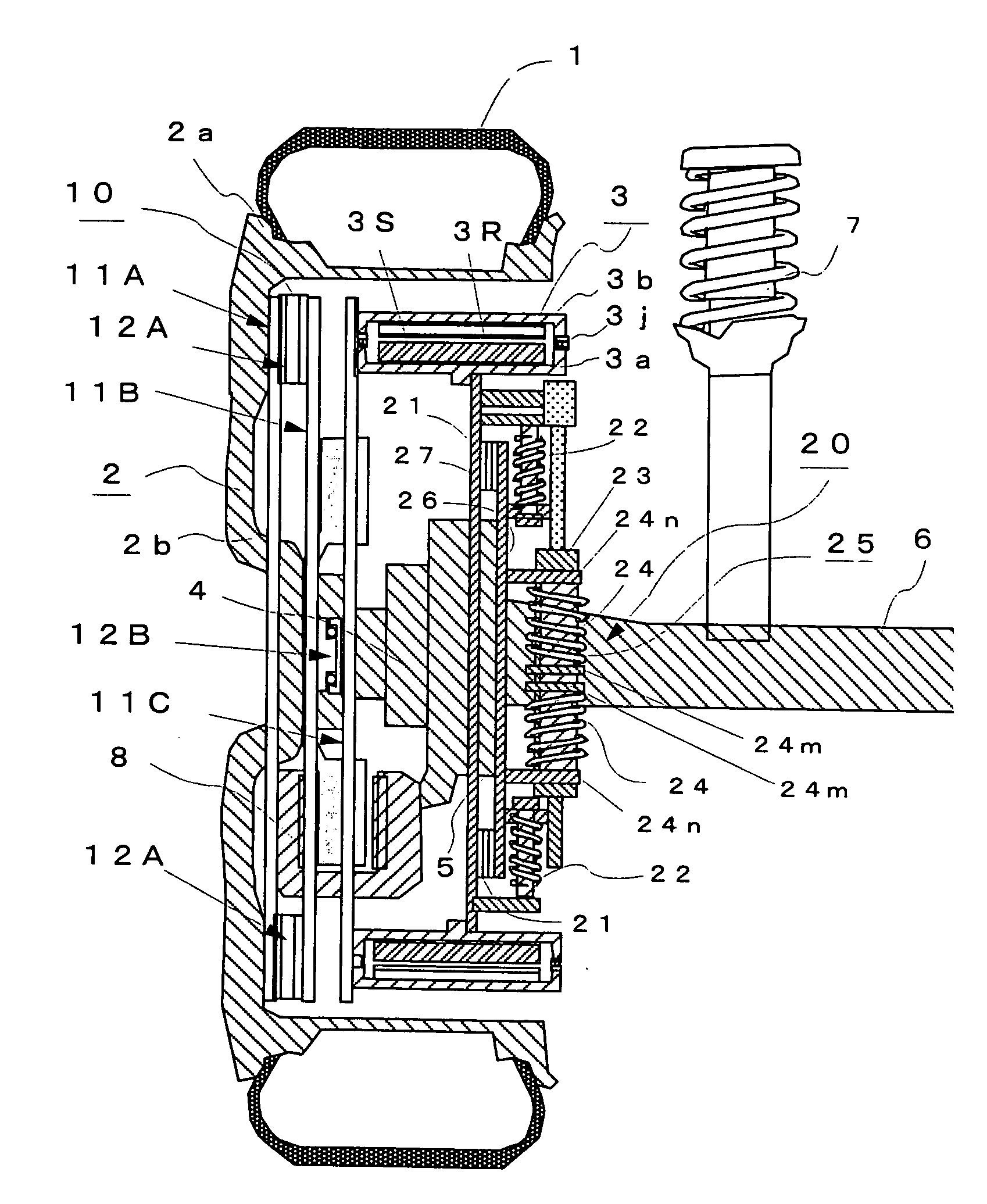
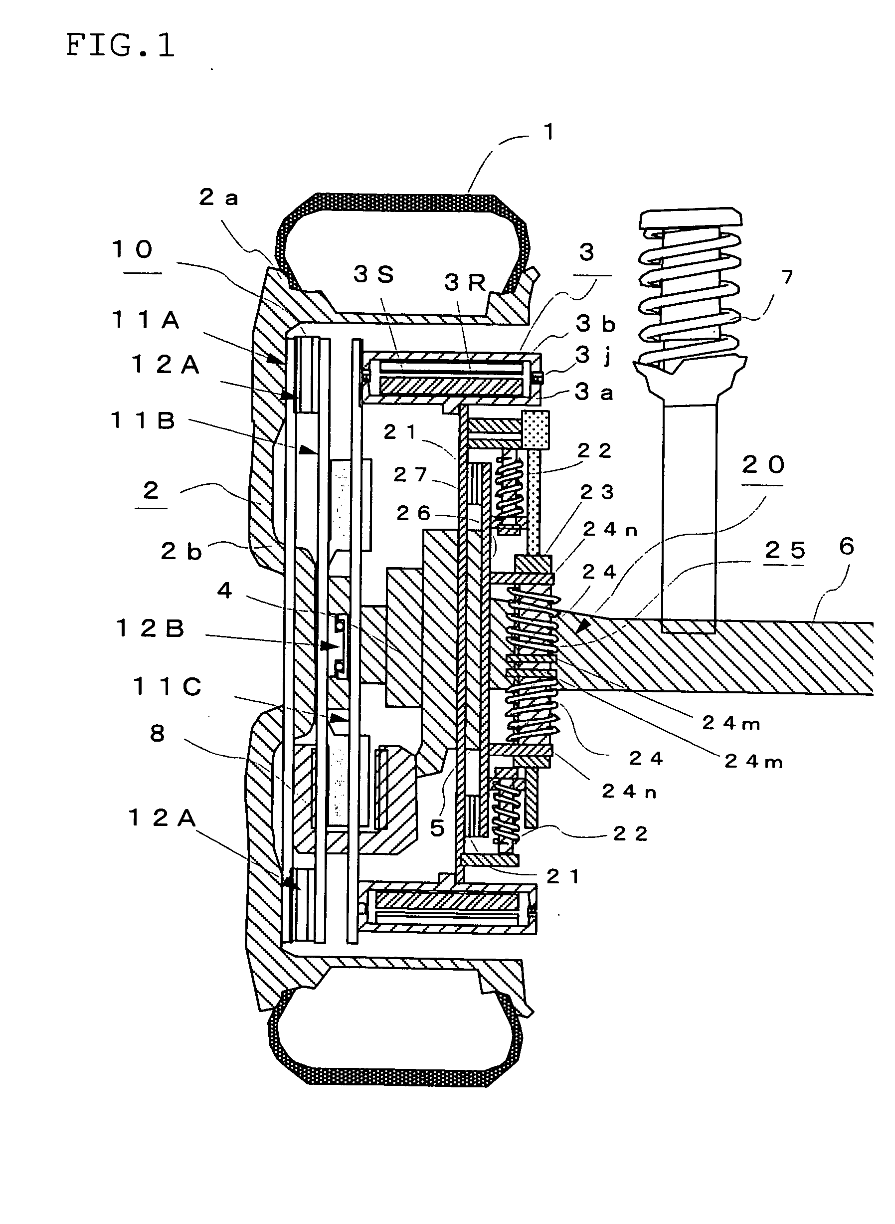
[0132]FIG. 1 is a diagram showing the constitution of an in-wheel motor system according to Embodiment 1. In FIG. 1, reference numeral 1 denotes a tire, 2 a wheel composed of a rim 2a and a wheel disk 2b, and 3 an outer rotor type in-wheel motor comprising a motor stator (to be referred to as “stator” hereinafter) 3S fixed to a non-rotating side case 3a installed on an inner side in the radial direction and a motor rotor (to be referred to as “rotor” hereinafter) 3R fixed to a rotating side case 3b rotatably connected to the above non-rotating side case 3a by a bearing 3j and installed on an outer side in the radial direction.

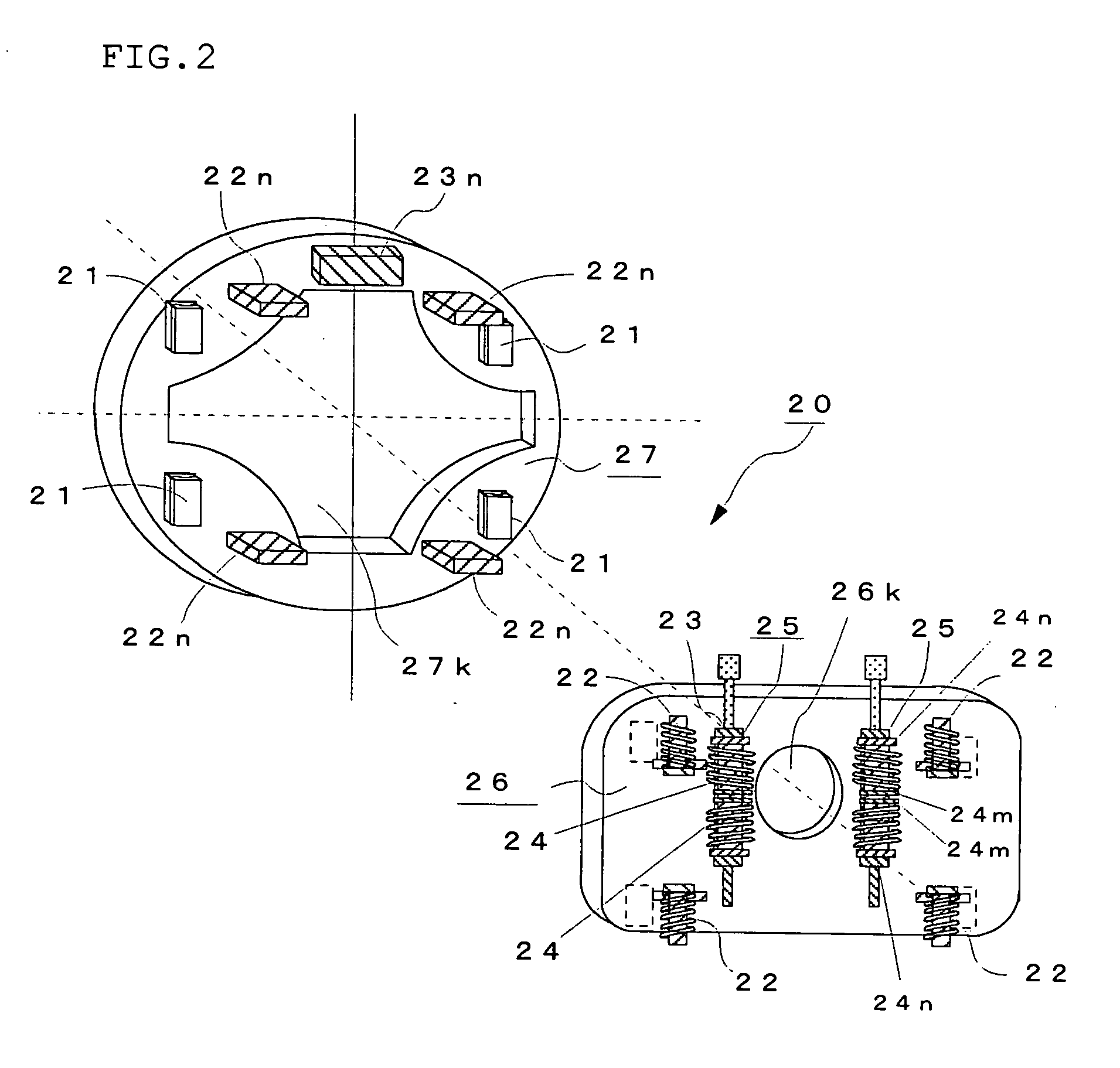
[0133] Numeral 4 denotes a hub portion connected to the rotary shaft of the wheel 2, 5 a knuckle connected to an axle 6, 7 a suspension member composed of a shock absorber or the like, 8 a brake unit mounted to the above hub portion 4, 10 a flexible coupling comprising a plurality of hollow disk-like plates 11A to 11C and direct-acting guides 12A and 12B for i...

embodiment 1-1

[0145] The table of FIG. 7 shows parameters indicative of the characteristic properties in the vertical direction of the vehicle for analyzing variations in ground-contact load which occur in the tire when the vehicle runs on a bad road, FIGS. 8(a), 8(b) and 9 to 11 show vibration models thereof, and FIG. 12 is a graph showing analytical results obtained from the vibration models.

[0146] Comparative Example 1 is an electric car which does not employ an ordinary in-wheel motor system and is represented by the vibration model of FIG. 8(a). In FIG. 8(a), as the motor is mounted on the car body side, the mass of the motor corresponds to the sprung mass Comparative Example 2 is an in-wheel motor car comprising an unsprung motor of the prior art which is represented by the vibration model of FIG. 8(b). This corresponds to FIG. 72.

[0147] Comparative Example 3 is a dynamic damper type in-wheel motor car in which a motor serves as a dynamic damper and which is represented by the vibration m...

example 1-2

[0156] The table of FIG. 13 shows parameters indicative of the characteristic properties in the horizontal direction of the vehicle for analyzing variations in longitudinal force which occur in the tire when the vehicle runs on a bad road, FIGS. 14(a) and 14(b) and FIGS. 15 to 17 show vibration models thereof, and FIG. 18 is a graph showing analytical results obtained from the above vibration models.

[0157] Comparative Example 1 is an electric car which does not employ an ordinary in-wheel motor system and is represented by the vibration model of FIG. 14(a). In FIG. 14(a), as the motor is mounted on the car body side, the mass of the motor corresponds to the sprung mass m2.

[0158] Comparative Example 2 is an in-wheel motor car comprising an unsprung motor of the prior art which is represented by the vibration model of FIG. 14(b). This corresponds to FIG. 47.

[0159] Comparative Example 3 is a dynamic damper type in-wheel motor car in which a motor serves as a dynamic damper and which...


PUM


Abstract

An in-wheel motor system, wherein the rotating side case 3b of an in-wheel motor 3 is connected to a wheel 2 by a flexible coupling 10 comprising a plurality of hollow disk-like plates 11A to 11C and direct-acting guides 12A and 12B, the non-rotating side case 3a of the motor 3 is connected to a knuckle 5 by a damping mechanism 20 for connecting the non-rotating side case 3a of the motor to the knuckle 5 which is a frame dress-up part of the vehicle, comprising two plates 26 and 27 whose moving directions are limited to the vertical direction of the vehicle by direct-acting guides 21 and which are interconnected by first spring elements 22 which move in the vertical direction of the vehicle and dampers 25 with a spring element, each comprising a damper 23 and a second spring element connected to the damper 23 in series and arranged parallel to the first spring elements 22, whereby the drive force of the in-wheel motor 3 can be transmitted to the wheel 2 without fail and the road holding properties of a vehicle can be further improved by greatly reducing variations in the ground-contact load of a tire.

Description

BACKGROUND OF THE INVENTION [0001] 1. Field of the Invention [0002] The present invention relates to an in-wheel motor system for use in vehicles having direct-drive wheels as drive wheels. [0003] 2. Description of the Prior Art [0004] In recent years, in a vehicle driven by a motor such as an electric car, an in-wheel motor system which incorporates a motor in wheels is being employed due to its high space efficiency and drive force transmission efficiency. The in-wheel motor of the prior art has a structure that a motor portion is fixed to a spindle shaft connected to a part called “upright” or “knuckle” which is a frame dress-up part of the vehicle so that a motor rotor and a wheel can turn. FIG. 72 shows the constitution of an in-wheel motor 80 disclosed by JP-A 9-506236 (the term “JP-A” as used herein means an “unexamined published Japanese patent application”). In this in-wheel motor 80, a rotor 8OR having magnet means (permanent magnet) 80M is installed in a housing 82 fixed ...

Claims


Application Information

Patent Timeline
Patent Type & Authority Applications(United States)
IPC IPC(8): B60G3/01B60G7/00B60G9/00B60K7/00
CPCB60G3/01B60K2007/0092B60G9/00B60G2200/30B60G2200/422B60G2202/12B60G2202/25B60G2204/124B60G2204/129B60G2204/149B60G2204/30B60G2204/4232B60G2206/50B60G2300/50B60K7/0007B60K2007/0038B60G7/008
Inventor NAGAYA, GO
Owner BRIDGESTONE CORP
Why Eureka
Try Eureka