Biosensors array and method for operating a biosensor array

Active Publication Date: 2005-11-10
BOEHRINGER LNGELHEIM VETMEDICA GMBH
View PDF10 Cites 95 Cited by
  • Summary
  • Abstract
  • Description
  • Claims
  • Application Information

AI Technical Summary

Benefits of technology

[0043] The problem is solved in accordance with one aspect of the invention by me

Problems solved by technology

An undesirable oxidation or reduction may have the effect, inter alia, that the chemical bonds entered into in the course of immobilization and hybridization are broken.
Furthermore, electrolysis may commence at the sensor electrodes, with the result that the electrolysis products bring the chemical milieu required for operation of the sensors out of the required equilibrium and lead to gas formation.
Realizing arrays with two-pole impedance sensors gives rise to the challenge that the signals of all the sensors have to be fed to a read-out device.
This

Method used


Image

  • Biosensors array and method for operating a biosensor array
  • Biosensors array and method for operating a biosensor array
  • Biosensors array and method for operating a biosensor array

Examples


Embodiment Construction

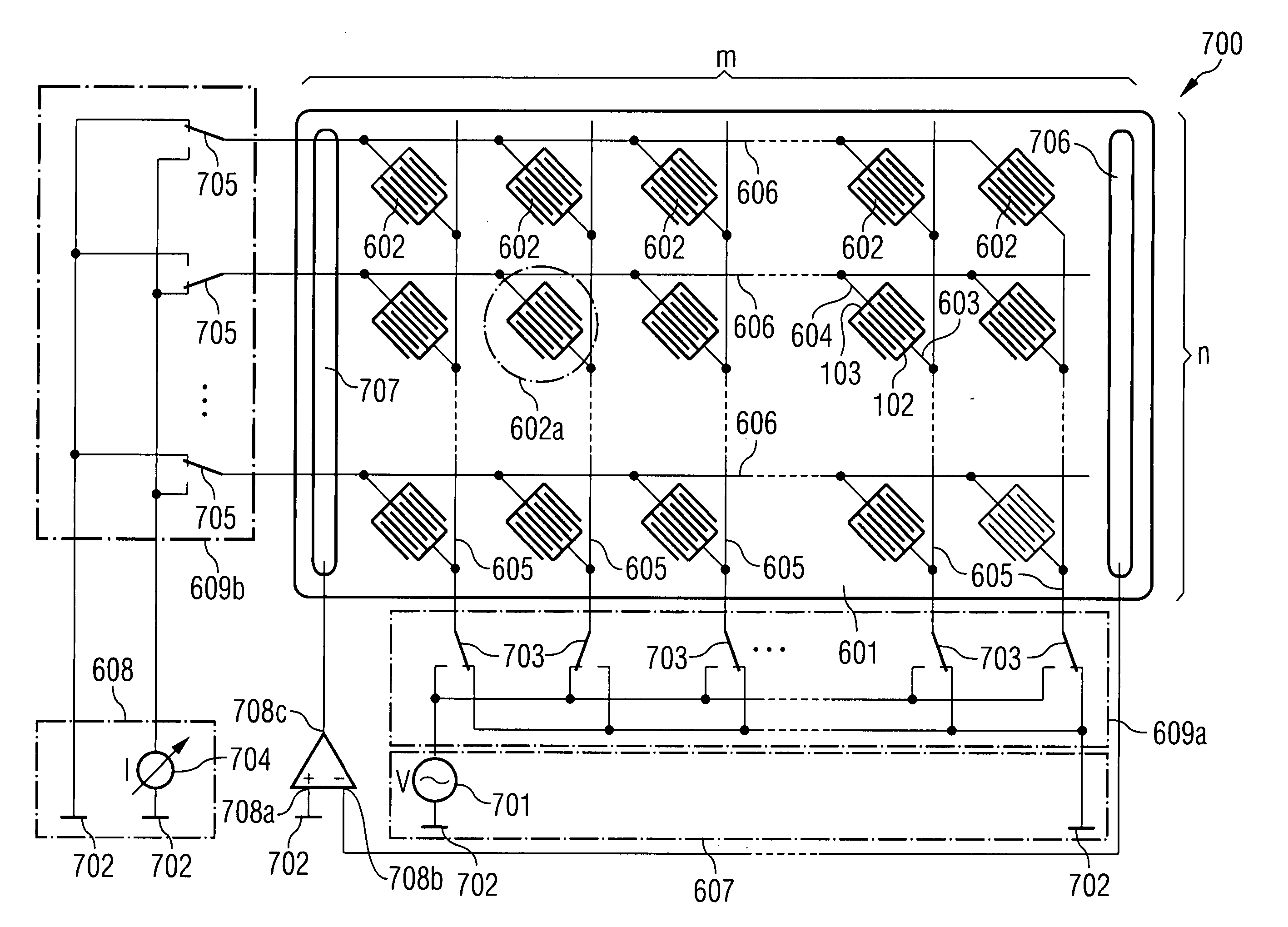
[0072] A basic idea of the invention consists in providing drive lines and detection lines that are provided jointly for in each case a plurality of biosensor zones of a biosensor array, thereby considerably reducing the number of signal lines required for operating the biosensor array. This makes it possible to operate a biosensor array (in particular on a passive chip) with a relatively small number of signal lines and a small number of pads coupled to the signal lines. This saves space on the biosensor array, which enables a higher integration density, and the production costs are reduced. The array architecture according to the invention is also of interest for active chips since it permits the circuitry outlay per biosensor zone to be kept low, which in turn enables the production of high-density arrays. In the case of active biosensor arrays, additional circuit devices (for example preamplifiers, AD converters, etc.) are provided on the substrate.

[0073] For a, by way of examp...


PUM

PropertyMeasurementUnit
Timeaaaaaaaaaa
Currentaaaaaaaaaa
Electric potential / voltageaaaaaaaaaa

Abstract

A biosensor array having a substrate, a plurality of biosensor zones arranged on the substrate, each of which has a first terminal and a second terminal, at least one drive line and at least one detection line, the at least one drive line being electrically insulated from the at least one detection line. In each case the first terminal of each biosensor zone is coupled to precisely one of the at least one drive line and the second terminal of each biosensor zone is coupled to precisely one of the at least one detection line, and at least one of the at least one drive line and at least one of the at least one detection line is coupled to at least two of the biosensor zones. The biosensor array also has a drive unit for providing an electrical drive signal, a detection unit for detecting an electrical detection signal resulting from the electrical drive signal, and a selection unit that couples the drive unit to the drive line of a biosensor zone to be selected and the detection unit to the detection line of the biosensor zone to be selected, whereby the biosensor zone is selected.

Description

CROSS-REFERENCE TO RELATED APPLICATION [0001] This application is a continuation of International Patent Application Serial No. PCT / DE2003 / 002094, filed Jun. 24, 2003, which published in German on Dec. 31, 2003 as WO 2004 / 001405 A1.FIELD OF THE INVENTION [0002] The invention relates to a biosensor array and a method for operating a biosensor array. BACKGROUND OF THE INVENTION [0003] Two-pole impedance sensors have been proposed for various fields of sensor technology. Such two-pole impedance sensors are described in WO 93 / 22678, DE 19610115 A1, U.S. Patent Ser. No. 60 / 007840, and Peter Van Gerwen et al., “Nanoscaled Interdigitated Electrode Arrays for Biochemical Sensors”, Proc. International Conference on Solid-State Sensors and Actuators (Transducers '97), pp. 907-910, 1997, for the area of biosensor technology, and Hagleitner, C. et al. “A Gas Detection System on a Single CMOS-Chip comprising capacity, calorimetric, and mass sensitive microsensors”, Proc. International Solid-Stat...

Claims


Application Information

Patent Timeline
IPC IPC(8): G01N33/53G01N27/02G01N27/327G01N27/403G01N27/416G01N33/487G01N37/00
CPCG01N27/3276
Inventor FREY, ALEXANDERHOFMANN, FRANZHOLZAPFL, BIRGITPAULUS, CHRISTIANSCHIENLE, MEINRADTHEWES, ROLAND
Owner BOEHRINGER LNGELHEIM VETMEDICA GMBH
Why Eureka
Try Eureka