
Connection mechanism and method

a technology of connection mechanism and connection mechanism, which is applied in the direction of manufacturing tools, transportation and packaging, and welding apparatus, etc., can solve the problem of significant greater connection force, and achieve the effect of significantly improving the strength of the resulting connection

Inactive Publication Date: 2005-11-10
REMMELE ENG
View PDF21 Cites 63 Cited by
  • Summary
  • Abstract
  • Description
  • Claims
  • Application Information

AI Technical Summary

Benefits of technology

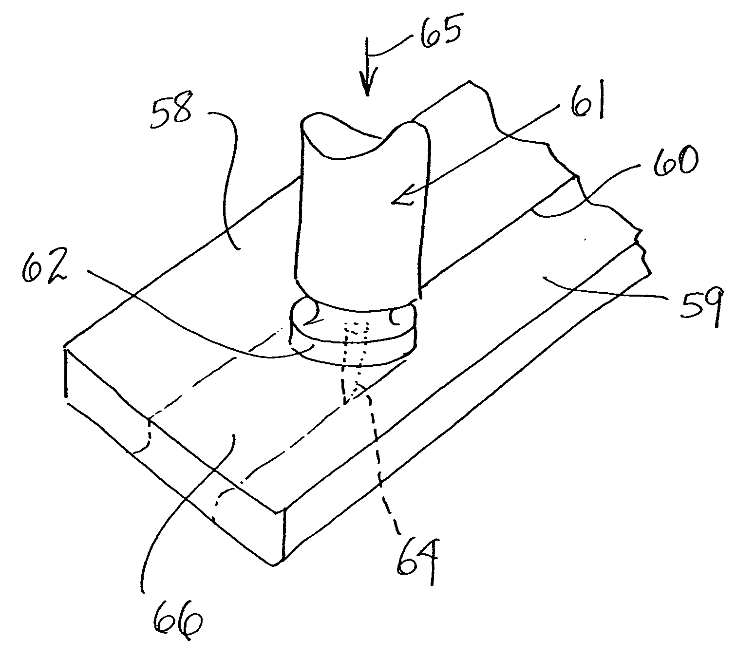
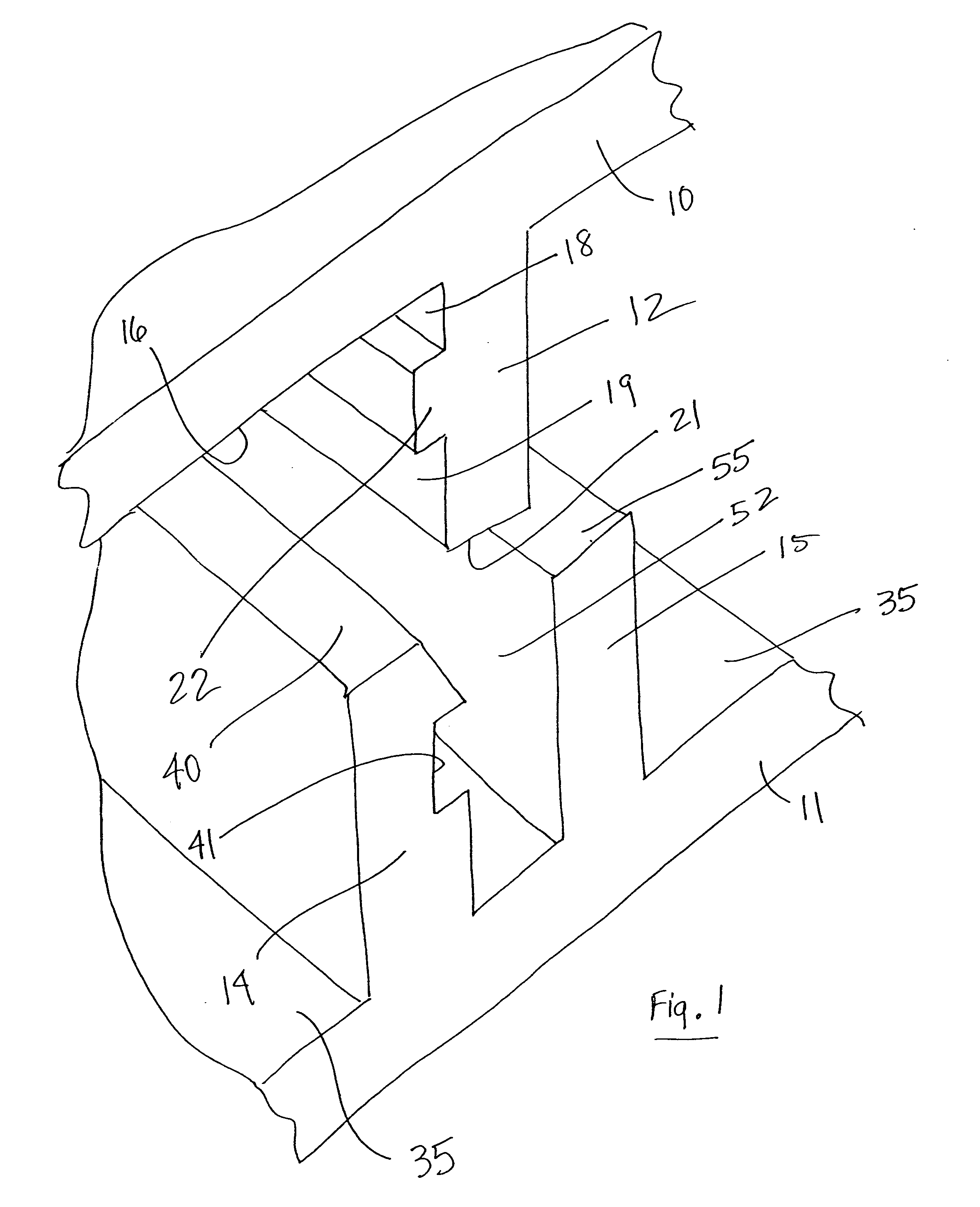
[0007] The present invention is directed to a connection mechanism and method for connecting two parts or members together with a precision, self-locking connection technique and the use of a self-locking connection technique in combination with a further connection technique such as friction stir welding, conventional welding, brazing and bonding to eliminate clamping or to otherwise retain the members during and / or after application of such further connection technique. This combination not only eliminates the need for clamping or otherwise retaining the elements in a fixed position during the application of such further connection technique, but because the self-locking connection mechanism remains after the further connection is completed, the strength of the resulting connection is significantly improved.
[0009] A further feature of the present invention is to utilize a self-locking connection mechanism such as the improved precision self-locking connection mechanism described above in combination with a further connection technique by providing a seam or joint between the two parts along which such further connection technique can be employed. Such a combination eliminates the need to use clamps or other external retaining means to maintain the two parts together during application of such other technique. Further, because the self-locking connection means is not removed after the application of such other connection technique, the combination results in a significantly greater connection force. Such other connection technique may include friction stir welding, conventional welding, brazing and bonding, among others.
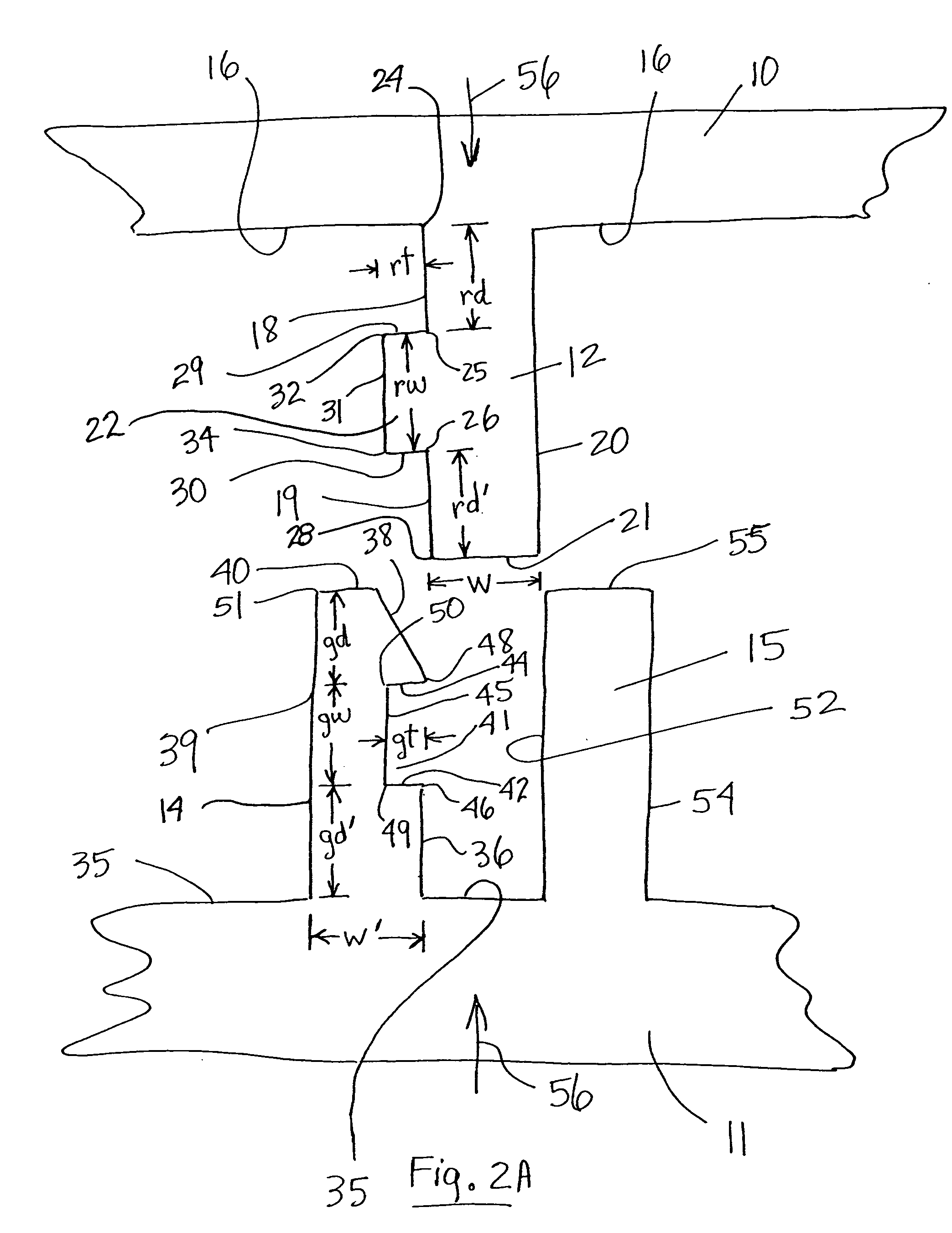
[0011] A further object of the present invention is to provide a precision self-locking connection mechanism in which the two members to be connected have mating connection members with close tolerances to maximize the connecting strength.

Problems solved by technology

Further, because the self-locking connection means is not removed after the application of such other connection technique, the combination results in a significantly greater connection force.

Method used


Image

  • Connection mechanism and method
  • Connection mechanism and method
  • Connection mechanism and method

Examples


Embodiment Construction

[0044] The present invention relates generally to an improved self-locking connection mechanism, by itself and in combination with a further connection mechanism, to connect two structural parts or members together. The invention also relates to a method of connecting two structural parts or members together utilizing a self-locking connection mechanism by itself and in combination with a further connection mechanism such as friction stir welding, conventional welding, brazing, bonding or the like.

[0045] As used herein, the term “self-locking” connection mechanism refers to a connection mechanism in which the connection, retaining or locking forces between two members result solely or substantially from the structural configuration of the respective elements themselves and do not rely on any external connection, retaining or locking means. While various self-locking connection mechanisms are covered by and fall within the scope of the present invention, both with respect to the sel...


PUM

PropertyMeasurementUnit
Fractionaaaaaaaaaa
Flexibilityaaaaaaaaaa

Abstract

A precision self-locking connection mechanism and method for connecting two parts or elements to one another and a precision self-locking connection mechanism and method in combination with a further connection mechanism for connecting two parts or elements together.

Description

BACKGROUND OF THE INVENTION [0001] 1. Field of the Invention [0002] The present invention relates generally to a connection mechanism and method, and more specifically to a connection mechanism for connecting two parts or members to one another without the need for bolts, rivets, screws, clamps or other such external connecting means. In one embodiment of the invention, the connection mechanism utilizes a self-locking connection mechanism to connect elements to one another. In a further embodiment of the invention, a self-locking connection mechanism and method is used in combination with a further connection mechanism such as friction stir welding (FSW), brazing, bonding or other connection techniques to further enhance the connection force and to seal the connecting joint or seam. [0003] 2. Description of the Prior Art [0004] A large number of what are commonly referred to as snap-in type or self-locking connection mechanisms are available in the art. Numerous examples exist of pl...

Claims


Application Information

Patent Timeline
IPC IPC(8): B23K1/00B23K20/12B23K33/00B29C65/58B29C65/72B64C3/26F16B5/08F16B11/00
CPCB23K20/122B29C65/483B23K33/004B29C65/0681B29C65/58B29C65/72B29C66/124B29L2031/3085B64C3/26F16B5/08F16B11/006B23K20/1265B29C65/48B29C66/542B29C66/54B29C65/02B29C65/00B29C66/8322B29C66/1222B29C66/1224B29C66/12449B29C66/12469
Inventor FRAZER, JAMES T.MORRI, TERRANCE L.
Owner REMMELE ENG
Learn More