Fuel injector

a fuel injector and injector technology, applied in the direction of liquid fuel feeders, machines/engines, mechanical equipment, etc., can solve the problems of fuel injector malfunction, solder or welding point tear, and the cable cannot be taut, so as to prevent a short circuit

Inactive Publication Date: 2005-11-10
ROBERT BOSCH GMBH +1
View PDF16 Cites 12 Cited by
  • Summary
  • Abstract
  • Description
  • Claims
  • Application Information

AI Technical Summary

Benefits of technology

[0002] The fuel injector according to the present invention has the advantage that an improvement is achieved in a simple manner to the effect that the service life of the fuel injector is increased in that the earth pole of the actuator is electrically connected to the ground terminal of the plug, and the positive pole of the actuator is connected to the positive terminal in a cable-less manner. This prevents malfunctioning of the fuel injector due to a cable fracture. Since two cables are omitted, space is saved, so that the fuel injector is able to have a smaller design.
[0003] It is particularly advantageous if the earth pole of the actuator is electrically connected to the ground terminal of the plug via the valve housing and / or an actuator housing, since this utilizes an already existing electrically conductive connection in the fuel injector. Furthermore, the ground contacting of the actuator reduces electromagnetic interference radiation of the actuator.
[0004] In addition, it is advantageous if the positive pole of the actuator is electrically connected to the positive terminal by way of the hydraulic coupler, since in this way the current supply to the actuator is implemented via an existing electrically conductive connection.
[0006] Furthermore, it is advantageous if the positive terminal of the plug is electrically connected to a head part of the hydraulic coupler, and the positive pole of the actuator is electrically connected to a foot part of the hydraulic coupler, the head part and the foot part of the hydraulic coupler in turn being interconnected in an electrically conducting manner via an elastic sealing element. This allows the current to be supplied by way of the hydraulic coupler.
[0007] It is advantageous if a first electrical insulation is provided between the hydraulic coupler and the actuator, and a second electrical insulation is provided between the hydraulic coupler and the valve housing since this prevents a short circuit.

Problems solved by technology

Due to the fact that the hydraulic coupler executes thermally caused compensating movements, the cables cannot be taut, but must be non-tensioned by providing additional length.
The cables are not allowed to be in contact with adjacent components, since the many compensating movements may otherwise cause them to fray over time.
It is disadvantageous that the compensating movements put heavy mechanical stress on the cables, so that a cable fracture as a result of material fatigue will occur after a predefined service life of the fuel injector, or the solder or welding points of the cables will tear.
This leads to malfunctioning of the fuel injector.

Method used


Image

  • Fuel injector
  • Fuel injector

Examples


Embodiment Construction

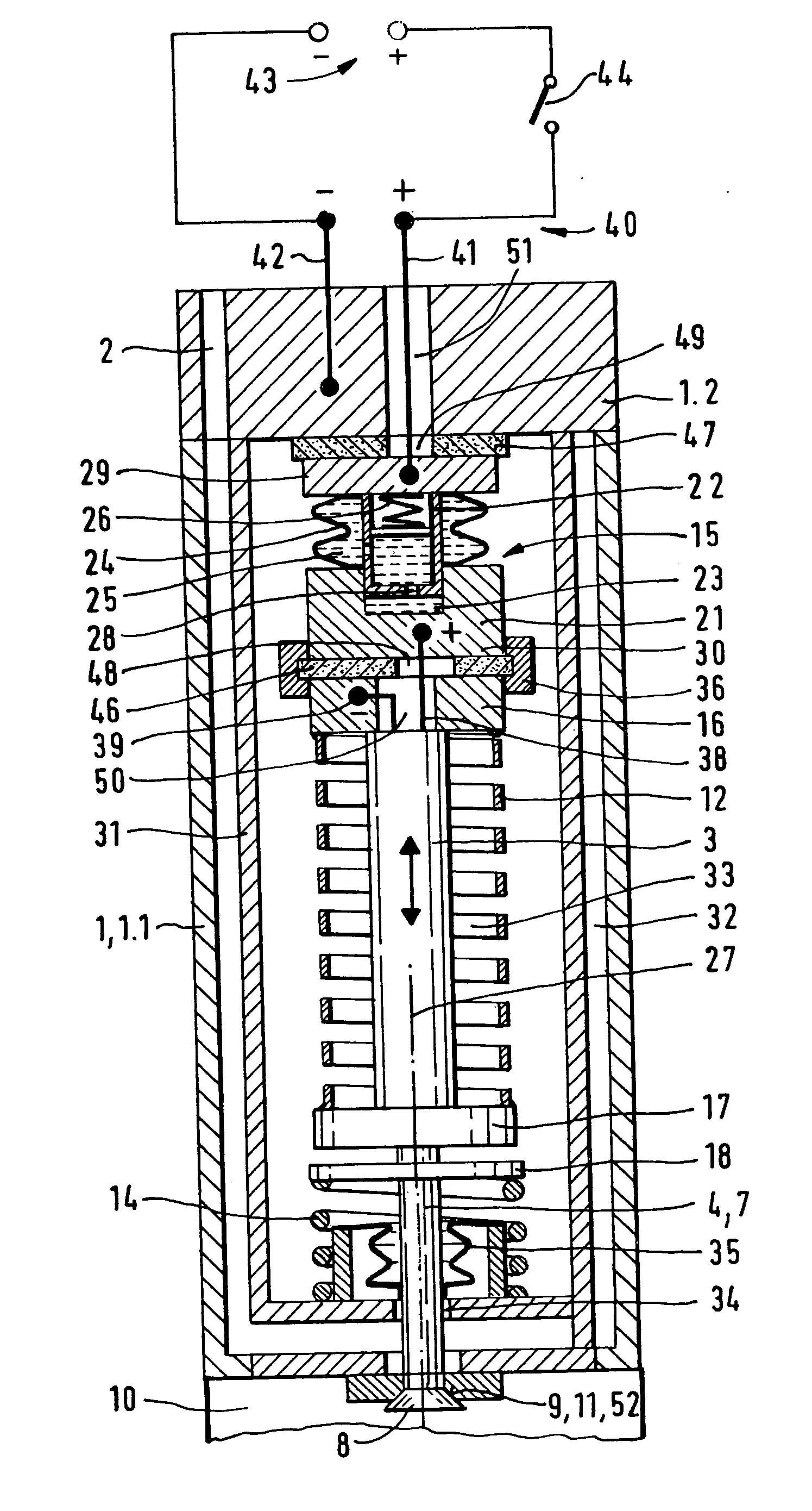
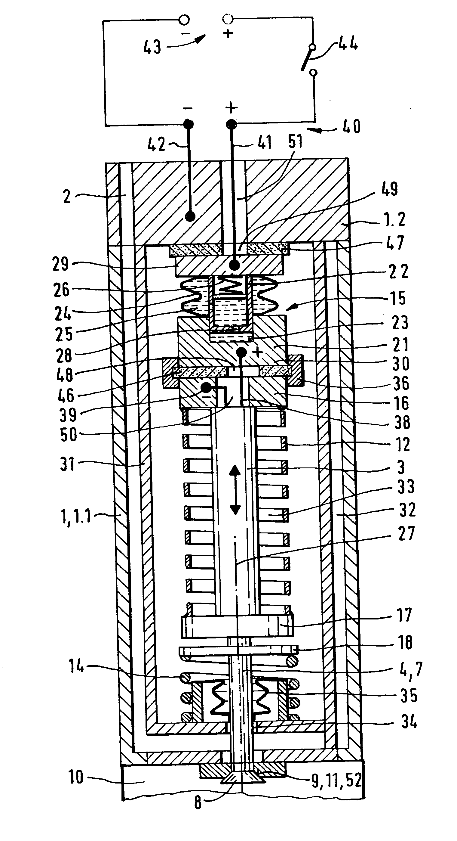
[0009] The fuel injector is used in the so-called direct injection, for instance, and injects fuel such as gasoline or diesel into a combustion chamber of an internal combustion engine.

[0010] The fuel injector has a valve housing 1 with an input port 2 for the fuel. The valve housing includes a housing component 1.1 in the shape of a cup, for instance, and a housing lid 1.2 sealing cup-shaped housing component 1.1. Input port 2 is provided in housing lid 1.2, for example.

[0011] A schematically illustrated actuator 3 such as a piezoelectric or magneto-restrictive actuator is arranged in valve housing 1 for the axial adjustment of a valve needle 4.

[0012] Valve needle 4 is provided in valve housing 1 so as to be axially displaceable, and has, for instance, a needle shaft 7 facing actuator 3, and a valve-closure member 8 facing away from actuator 3. Actuator 3 transmits its movement to needle shaft 7 of valve needle 4, which causes valve-closure member 8 cooperating with a valve seat...


PUM


Abstract

Known fuel injectors have a valve housing in which an actuator and an hydraulic coupler are arranged, an electrical plug being provided on the valve housing for contact with a voltage source. The cables running from the plug to the actuator must be guided around the coupler to the actuator. It is disadvantageous that the compensating movements put heavy mechanical stress on the cables, so that a cable fracture as a result of material fatigue occurs after a predefined service life of the fuel injector, or that the solder or welding points of the cables tear. This leads to malfunctioning of the fuel injector. In the present fuel injector, the service life is increased by the provision of connections without cables. The earth pole of the actuator is electrically connected to the ground terminal of the plug in a cable-less manner, and the positive pole of the actuator is electrically connected to the positive terminal in a cable-less manner.

Description

BACKGROUND INFORMATION [0001] A fuel injector having a valve housing in which a piezoelectric armature and an hydraulic coupler are arranged has already been proposed in German Patent Application No. 103 60 449, the piezoelectric actuator having a positive pole and an earth pole, an electrical plug with a positive terminal and a ground terminal being provided on the valve housing for the contacting with a voltage source. Via a cable in each case, the positive pole of the piezoelectric actuator is connected to the positive terminal of the plug, and the earth pole of the piezoelectric actuator is connected to the ground terminal of the plug. Since the hydraulic coupler between the valve housing and the actuator is arranged in a section of the fuel injector that faces the plug, the cables originating from the plug must be guided around the coupler to reach the actuator. Due to the fact that the hydraulic coupler executes thermally caused compensating movements, the cables cannot be tau...

Claims


Application Information

Patent Timeline
Patent Type & Authority Applications(United States)
IPC IPC(8): F02M51/00F02M51/06F02M61/16H01L41/00
CPCF02M51/005F02M61/167F02M51/0603
Inventor LISKOW, UWE
Owner ROBERT BOSCH GMBH
Why Eureka
Try Eureka