
High-speed frame transfer of sub-frame area

a high-speed frame transfer and sub-frame technology, applied in the field of charge coupled devices, can solve the problems of limited high-speed readout of a standard ccd camera, slowing down the pace at which successive images can be acquired and digitized, and not being practical to have different size ccds to accommodate, etc., to achieve the effect of increasing the frame readout ra

Inactive Publication Date: 2005-11-10
ROPER SCI
View PDF12 Cites 16 Cited by
  • Summary
  • Abstract
  • Description
  • Claims
  • Application Information

AI Technical Summary

Benefits of technology

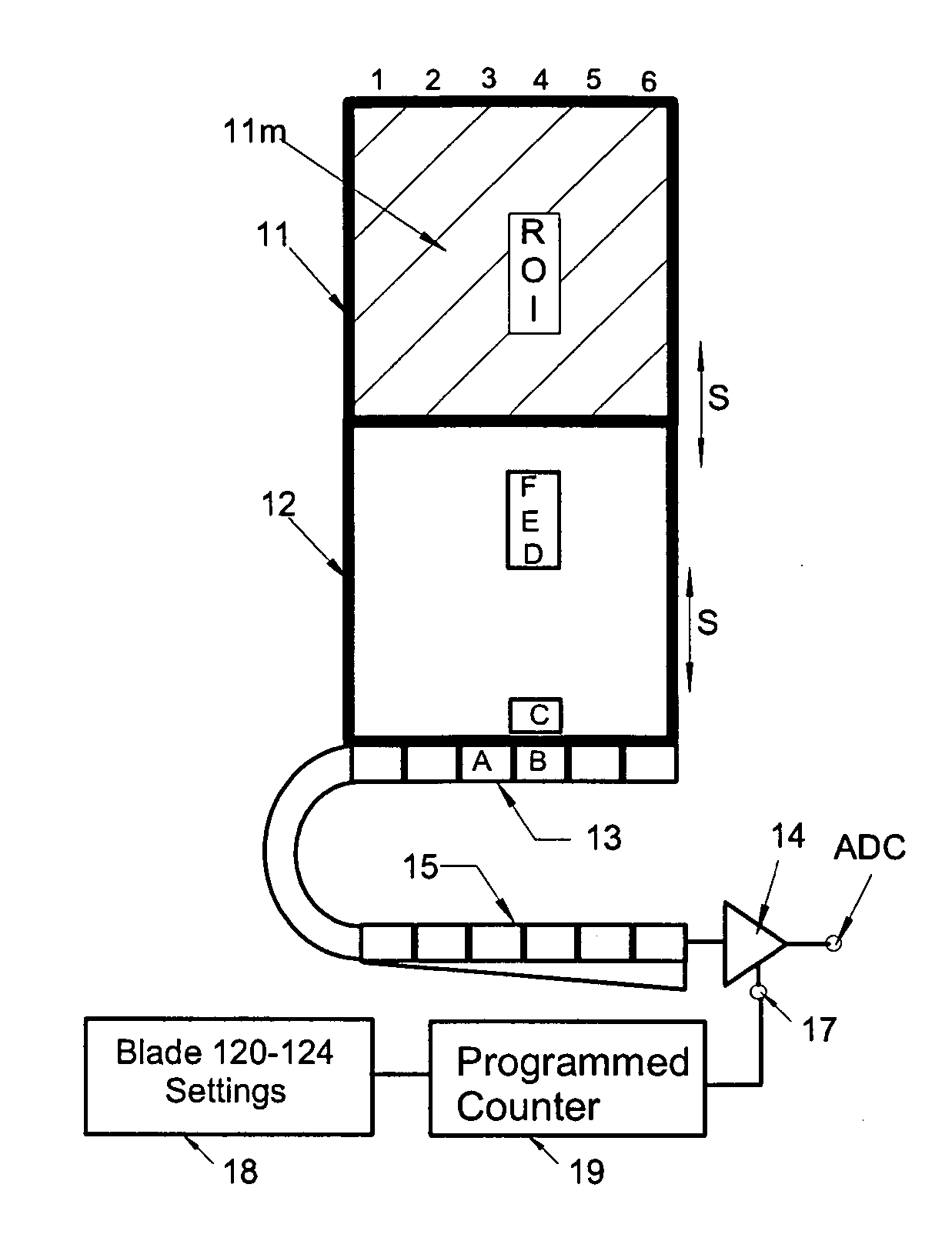
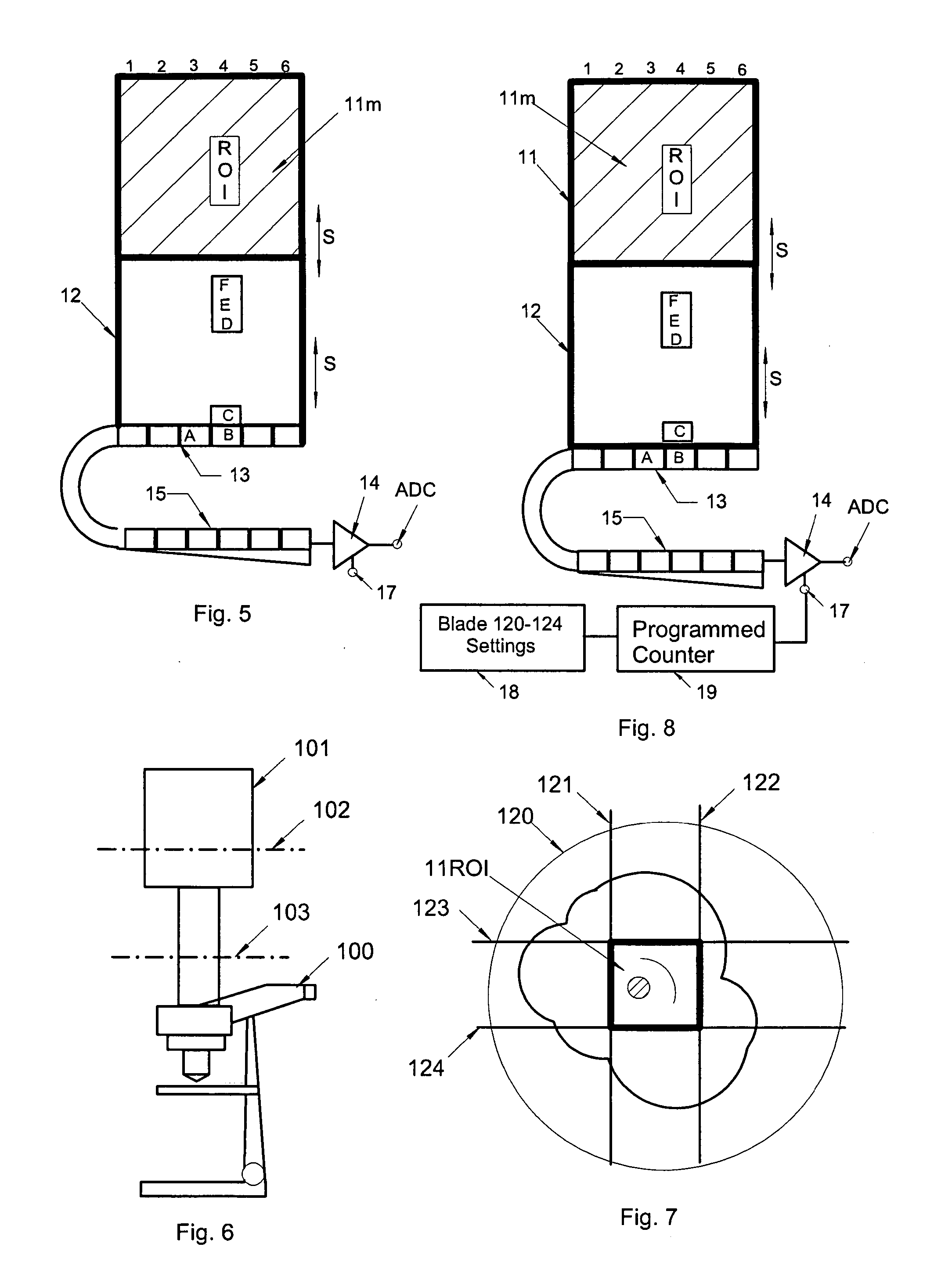
"The invention is about a method to increase the readout rate of a small, dimly illuminated region of interest (ROI) in a camera. The method involves programming the camera to operate as if it were a mini-CCD with fewer rows and pixels, and then serially passing all pixels through a serial register. The readout pattern is specified so that an integral number of images and spacers are fitted along the depth of the CCD beneath the frame transfer mask. The method requires that the region outside of the ROI be masked to prevent light contamination of the rest of the CCD area. The readout pattern ensures that the ROI is completely under the mask and that the next frame can begin without shifting the entire CCD. The method results in a series of valid ROIs separated by a series of spacer regions, which should equal the number of rows under the frame storage mask. The method requires a frame transfer type CCD architecture so that exposure and readout cycles can be overlapped and the selective illumination of the ROI only. The technical effect of the invention is to increase the readout rate of a small, dimly illuminated ROI in a camera."

Problems solved by technology

High speed readout of a standard CCD camera is limited by the analog to digital conversion rate and by the number of CCD pixels that must be digitized.
Moreover, there is considerable overhead in shifting and readout that slows down the pace at which successive images can be acquired and digitized.
Unfortunately, because the ROI will usually be of a different size for different observations it would not be practical to have different size CCDs to accommodate all of the possibilities.
However, even with all but a small portion of the CCD surface masked off, the speed of analog to digital conversion is still limited by the need to shift the same number of times as for an entire CCD.
As the ROI gets smaller, however, there is a fundamental overhead incurred in pixel shifting and dumping that limits the overall speed of readout.
The time required to do all this shifting, digitization and dumping creates a barrier to achieving higher frame rates.
The difficulty of achieving fast readout is further exacerbated when the intensity of the signal within the ROI is very low because the accumulated signal is smaller than the readout noise of the cameras electronics.
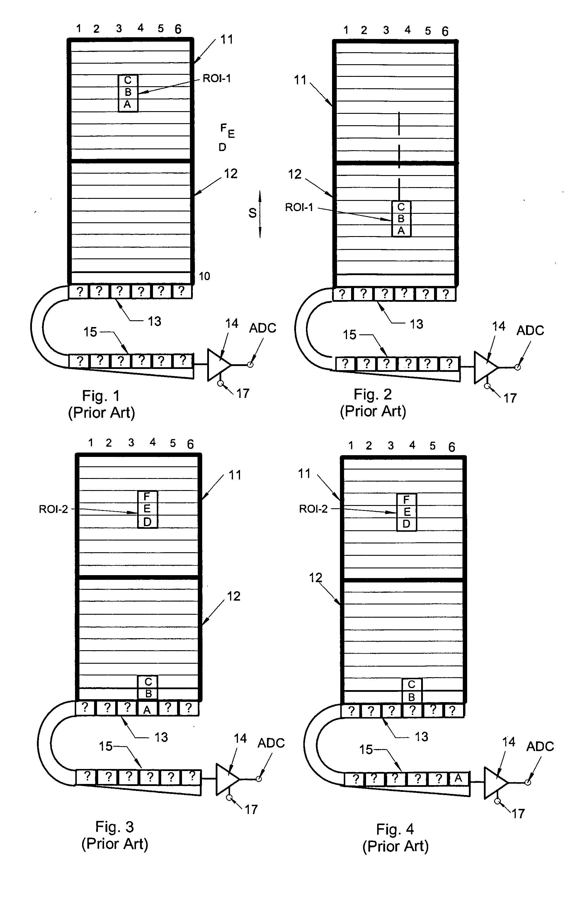
The process of moving the charge through the extended serial register 15 adds to processing overhead time and further slows down the image encoding process.

Method used


Image

  • High-speed frame transfer of sub-frame area
  • High-speed frame transfer of sub-frame area
  • High-speed frame transfer of sub-frame area

Examples


Embodiment Construction

[0016] Referring now to FIG. 1, as mentioned above, a conventional frame transfer CCD has an upper portion 11 that can be exposed to light from an object and a lower or storage portion 12 that is shielded from light. After a suitable exposure time is completed, the charges accumulating on the rows of polysilicon pixels in upper portion 11 are shifted down the parallel columns 1-6 into the shielded storage area 12, as shown in FIG. 2. Let it be assumed that all one is interested in is the region of interest ROI-1 comprising pixel rows A, B, C. Nevertheless, each row of pixels ahead of rows A, B, C must be shifted down the length of storage region 12 before the pixels of the next row can be entered into register 13. The same applies to row A of the region of interest which, as shown in FIGS. 3 and 4 must also be shifted along the entire length of serial output register 13 before the pixels of row B can be entered.

[0017] Once all of the rows of the image region ROI-1 have been shifted...


PUM


Abstract

In accordance with the invention, a region of interest (ROI) acquired by a frame transfer CCD is read out as quickly as if the imaging area of the CCD were no larger than the ROI. The imaging area of the CCD outside of the ROI is masked, preventing light from contaminating the rest of the imaging area. After a suitable exposure time the image pixels of the ROI are shifted into the storage region of the frame transfer CCD. Once the ROI is under the mask in the storage region, the next exposure may begin, and so too does the image readout. Now the CCD shifts exactly the number of rows in the ROI into the serial register one at a time and digitizes the number of pixels in each row. This process results in a series of valid ROIs separated by a series of spacer regions pipelining down the storage region of the CCD. As an example, using a standard frame transfer mode of operation, a commercially available frame transfer camera (IPentaMAX) can achieve 83 FPS on a 50×50 ROI. In accordance with this invention, a 50×50 ROI can be read out at 877 FPS

Description

FIELD OF THE INVENTION [0001] This invention relates to charge coupled devices and, more particularly, to an arrangement for high speed readout of a small area of interest in the image acquired by the charge coupled device. BACKGROUND OF THE INVENTION [0002] Digital cameras utilize a charge coupled device (CCD) to convert photons into an electronic signal that can be measured. In full frame imaging, the photons are collected on discreet elements referred to as pixels and then the charges that accumulate in the pixels are read out by the camera electronics. The process of readout typically requires the collected charges to be shifted in parallel rows down the columns of the image CCD sensor into a serial register at the bottom of the CCD. While the rows of charges are being shifted into the serial register, the CCD must be shuttered to avoid blurring the image. The rows of charges entered into the serial register are shifted along to a read out amplifier that measures the charges one...

Claims


Application Information

Patent Timeline
Patent Type & Authority Applications(United States)
IPC IPC(8): G02B21/00H04N3/14H04N25/72
CPCH04N5/335H04N3/1562H04N25/443H04N25/00H04N25/72
Inventor CHRISTENSON, MARK
Owner ROPER SCI
Learn More