Heat sink assembly with rotatable fins

a technology of heat sink and heat sink assembly, which is applied in the direction of electrical apparatus casing/cabinet/drawer, semiconductor/solid-state device details, instruments, etc., can solve the problems of limited space for the outlet, limited heat dissipation efficiency of the heat dissipation fin b>12/b>, and limited heat dissipation efficiency of the heat sink. , to achieve the effect of enhancing the heat dissipation efficiency of the heat sink

Active Publication Date: 2005-11-10
ASUSTEK COMPUTER INC
View PDF8 Cites 15 Cited by
  • Summary
  • Abstract
  • Description
  • Claims
  • Application Information

AI Technical Summary

Benefits of technology

[0009] To achieve the above, a heat sink assembly with rotatable fins of the invention includes a housing, a first heat dissipating device, a rod, an elastic member and a lever. The housing has a first sidewall and a second sidewall opposite to the first sidewall. The first sidewall has a first hole, a first sliding hole and a stop portion. The second sidewall has a second hole and a second sliding hole. The first heat dissipating device located in the housing has at least one third hole, a first protrusion and a second protrusion. The first protrusion slides in the first sliding hole and the second protrusion slides in the second sliding hole. The first protrusion and the second protrusion cause the first heat dissipating device to rotate between a first position and a second position. The rod passes through the first hole, the second hole and the third hole. The first heat dissipating device rotates between the first position and the second position with the rod as a rotating center. The elastic member has a first end connecting with the stop portion and a second end connecting with the first protrusion, and provides elasticity for the first protrusion to move the first heat dissipating device back to the first position. The lever is pivoted on an external side of the second sidewall, and the lever moves with the second protrusion.
[0010] In addition, the invention also discloses an electrical apparatus including a first casing, a second casing and a heat sink assembly. The second casing is pivoted on the first casing and the second casing is opposite to the first casing. The heat sink assembly is contained in the second casing. The heat sink assembly includes a housing, a first heat dissipating device, a rod, an elastic member and a lever. The housing has a first sidewall and a second sidewall opposite to the first sidewall. The first sidewall has a first hole, a first sliding hole and a stop portion. The second sidewall has a second hole and a second sliding hole. The first heat dissipating device located in the housing has at least one third hole, a first protrusion and a second protrusion. The first protrusion slides in the first sliding hole and the second protrusion slides in the second sliding hole. The first protrusion and the second protrusion cause the first heat dissipating device to rotate between a first position and a second position. The rod passes through the first hole, the second hole and the third hole. The first heat dissipating device rotates between the first position and the second position with the rod of being a rotating center. The elastic member has a first end connecting with the stop portion and a second end connecting with the first protrusion, and provides elasticity for the first protrusion to move the first heat dissipating device back to the first position. The lever is pivoted on an external side of the second sidewall, and the lever moves with the second protrusion.
[0011] As mentioned above, the heat sink assembly with rotatable fins or the electrical apparatus using this heat sink assembly according to the invention has a rotatable heat dissipating device. Compared to the prior art, the heat sink assembly and the electrical apparatus including the rotatable heat dissipating device can enlarge the heat dissipation space of the heat dissipating device, enhance the heat dissipation efficiency of the heat sink assembly, effectively lower the temperature of the electrical apparatus, prevent the electrical apparatus from being overheated owing to the poor heat dissipation effect, and thus ensure the quality of the electrical apparatus. In addition, the rotatable heat dissipating device of the invention cannot be rotated until the first casing and the second casing are opened. When the electrical apparatus is not used, the first casing and the second casing cover and close each other. In this case, the rotatable heat dissipating device is not exposed from the electrical apparatus, which does not interfere the user's convenience of carrying the electrical apparatus. Furthermore, the rotatable heat dissipating device is free from being collided, and the broken condition of the rotatable heat dissipating device can be avoided.

Problems solved by technology

In addition, the space for the outlet 112 is also limited such that the heat dissipation fins 12 cannot get a larger heat dissipation space and the heat dissipation efficiency of the heat dissipation fins 12 is thus limited.
Consequently, the electrical components in the notebook computer tend to be damaged because the environmental temperature is too high and the electrical components are thus overheated, thereby reducing the quality of the notebook computer.

Method used


Image

  • Heat sink assembly with rotatable fins
  • Heat sink assembly with rotatable fins
  • Heat sink assembly with rotatable fins

Examples


Embodiment Construction

[0020] Other objects, features, and advantages of the invention will become apparent from the following detailed description of the preferred but non-limiting embodiments. The heat sink assembly with rotatable fins and the electrical apparatus with the heat sink assembly according to the embodiment of the invention will be made with reference to the accompanying drawings.

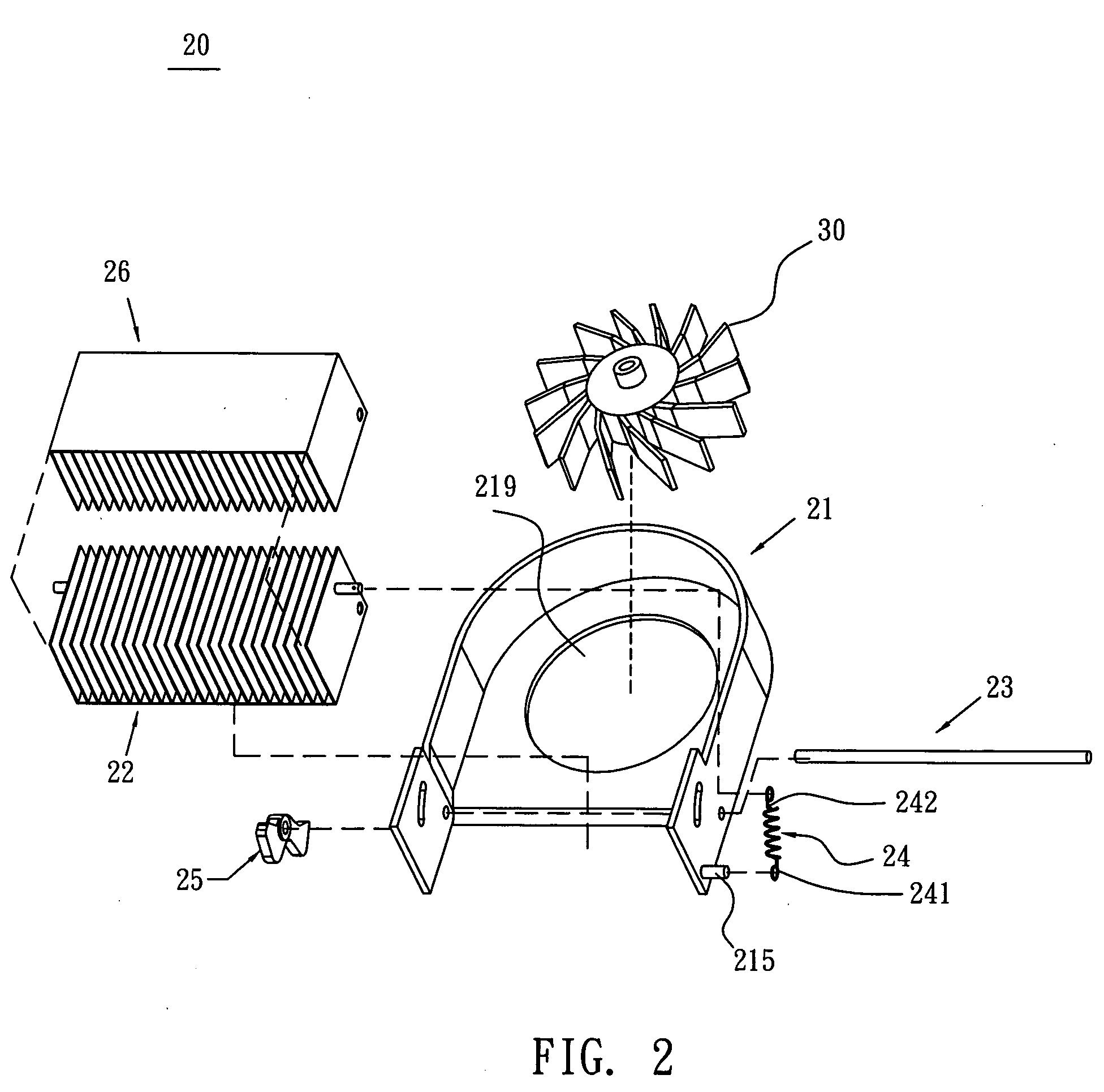
[0021] Firstly, please refer to FIGS. 2 to 4 to illustrate a heat sink assembly with rotatable fins according to the embodiment of the invention. In this embodiment, a notebook computer equipped with a heat sink assembly having rotatable fins will be described as an example. Of course, the heat sink assembly of the invention also can be equipped in other products.

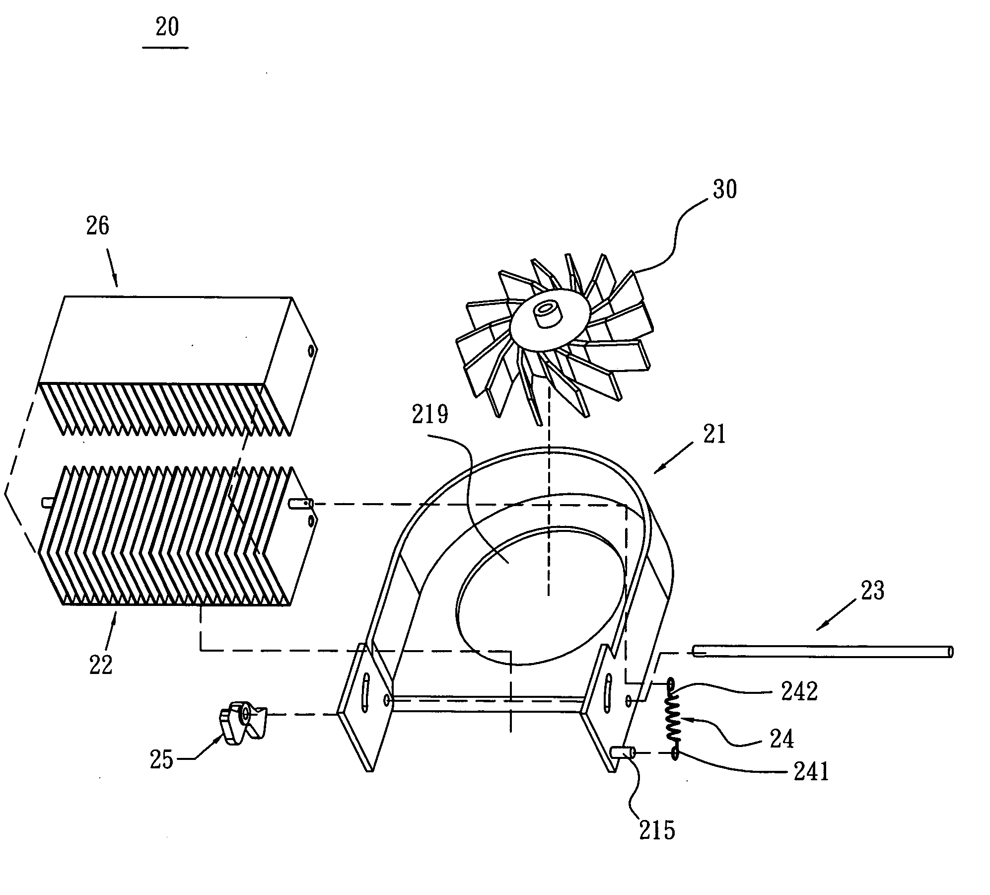
[0022] Referring to FIG. 2, a heat sink assembly 20 with rotatable fins includes a housing 21, a first heat dissipating device 22, a rod 23, an elastic member 24 and a lever 25.

[0023] Referring to FIG. 3, the housing 21 has a first sidewall 211 and a sec...


PUM


Abstract

A heat sink assembly having rotatable fins includes a housing, a first heat dissipating device, a rod, an elastic member and a lever. The housing includes a first sidewall having a first hole, a first sliding hole and a stop portion, and a second sidewall having a second hole and a second sliding hole. The first heat dissipating device is in the housing and has a third hole, a first protrusion sliding in the first sliding hole, and a second protrusion sliding in the second sliding hole. The rod passes through the first, second and third holes. The first heat dissipating device rotates between a first position and a second position with the rod of being a rotating center. A first end of the elastic member connects with the stop portion, and a second end thereof connects with the first protrusion. The lever moves with the second protrusion.

Description

BACKGROUND OF THE INVENTION [0001] 1. Field of Invention [0002] The invention relates to a heat sink assembly, and more particularly to a heat sink assembly with rotatable fins and an electrical apparatus using the heat sink assembly to enlarge or extend the space for dissipating heat more quickly & more efficacious. [0003] 2. Related Art [0004] Notebook computers have been widely used among the current information products because they have the main advantage of good mobility and capable of being portable according to requirements of users. In the highly developed and advanced information technology, a notebook computer may serve as a mobile workstation capable of enabling the network information acquisition and transmission and the database management. So, the notebook computer is the best choice for implementing the mobile office. In addition to the consideration of the software pack, the notebook computer still has to take the human-oriented operations into important considerati...

Claims


Application Information

Patent Timeline
Patent Type & Authority Applications(United States)
IPC IPC(8): G06F1/20H01L23/467
CPCG06F1/20H01L23/467H01L2924/0002H01L2924/00
Inventor LIN, YUNG KUN
Owner ASUSTEK COMPUTER INC
Why Eureka
Try Eureka