Edge detecting method

Active Publication Date: 2005-11-10
INTELLECTUAL VENTURES II
View PDF20 Cites 20 Cited by
  • Summary
  • Abstract
  • Description
  • Claims
  • Application Information

AI Technical Summary

Benefits of technology

[0021] The present invention can detect an edge by using the RGB Bayer signal prior to the color interpolation, without using the brightness signal (Y). Thus, the image is not affected by the noise occur

Problems solved by technology

Meanwhile, a fixed pattern noise occurs in the image sensor due to an offset voltage, which is caused by a minute difference in the manufacturing process.
However, the conventional edge detecting and correcting method does not consider a noise caused by a detective pixel or the imaging devices (the pixel array 10

Method used


Image

  • Edge detecting method
  • Edge detecting method
  • Edge detecting method

Examples


Embodiment Construction

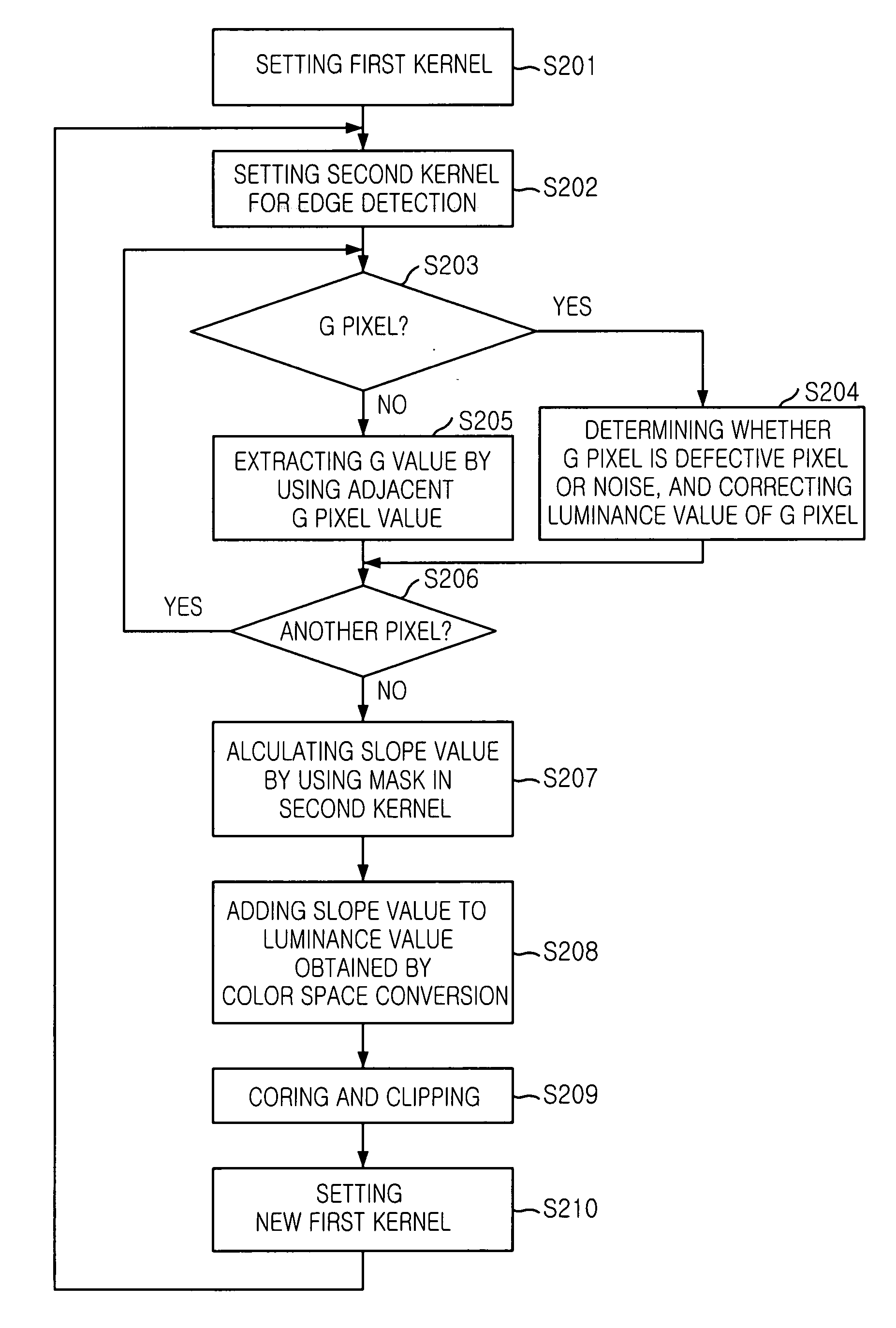
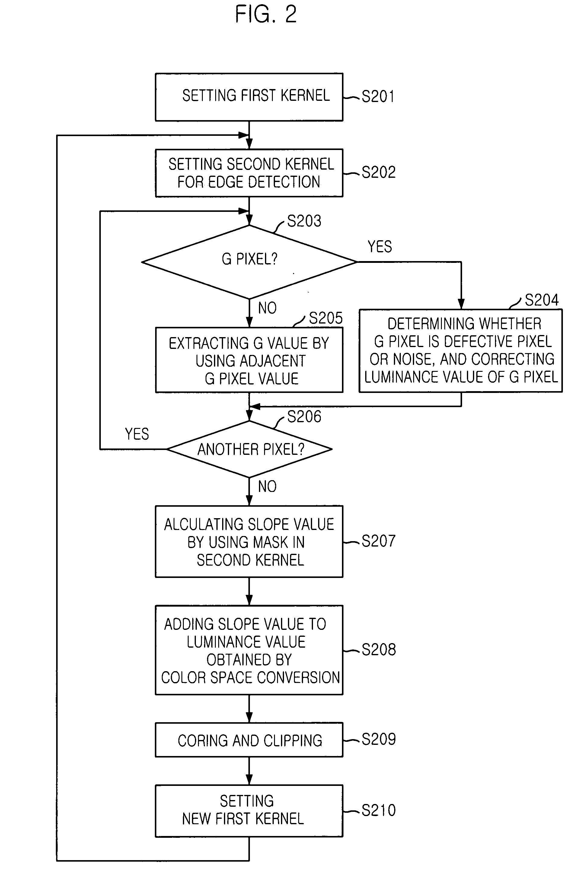
[0028] Hereinafter, the present invention will be described in detail with reference to the accompanying drawings.

[0029]FIG. 2 is a flowchart illustrating an edge detecting method in accordance with an embodiment of the present invention.

[0030] Referring to FIG. 2, in step S201, a first kernel (for example, a 5×5 kernel) is set based on a center pixel in pixel data of a mosaic arrangement so as to detect an edge. This process is aimed to interpolate a G value because the respective pixels have a luminance value only in one specific color in a color filter array (hereinafter, referred to as a CFA).

[0031] In step S202, a second kernel (for example, a 3×3 kernel) is set within the first kernel, based on the center pixel. In step S203, G values of all pixels in the second kernel are interpolated using the G pixel (pixel having a luminance value in a green component) of the first kernel. In this manner, the G value is interpolated and the edge is detected using the interpolated G valu...


PUM


Abstract

There is provided an edge detecting method, which is capable of preventing a noise influence caused by imaging device and a color interpolation. The edge detecting method includes the steps of: setting a first kernel based on a center pixel in pixel data arranged in a mosaic structure; setting a second kernel based on the center pixel within the first kernel; detecting whether a pixel having a green value in the second kernel is a defective pixel, and correcting the pixel; converting all pixels of the second kernel into pixels having green value; calculating a slope value by using a mask for detecting an edge in the second kernel; and detecting an edge by adding the slope value to a luminance value obtained by a color space conversion.

Description

FIELD OF THE INVENTION [0001] The present invention relates to a method for processing an image signal; and, more particularly, to a method for detecting an edge of an image signal. DESCRIPTION OF RELATED ART [0002] An image sensor can be used in various fields, such as a cell phone, a personal computer (PC) camera, a medical science, a toy, and so on. That is, the image sensor is widely used in all fields where an image signal is used. [0003] Such an image sensor captures an image of an object and the captured image is displayed on a screen. A picture quality of the displayed image is largely determined depending on a sharpness of an edge. Accordingly, various correction methods for improving the sharpness of the edge of the image have been proposed. [0004]FIG. 1 is a schematic block diagram of a conventional image sensor. [0005] Referring to FIG. 1, the conventional image sensor includes a control and external system interface 11, a pixel array 10, an analog-to-digital converter (...

Claims


Application Information

Patent Timeline
IPC IPC(8): H04N5/217G06K9/34G06K9/40G06K9/48G06T5/00H04N9/64
CPCG06T7/0085H04N2209/046H04N9/045G06T2207/20192G06T7/13E01F9/619
Inventor SONG, DONG-SEOBAHN, HYUN-JOO
Owner INTELLECTUAL VENTURES II
Why Eureka
Try Eureka