Metabolically efficient leg brace

a leg brace and metabolic technology, applied in the field of metabolic efficiency leg braces, can solve the problems of not allowing the wearer to supplement the torso support, energy being added to the torso, energy being extracted from the torso, etc., and achieve the effect of minimizing the power drain of the battery

Inactive Publication Date: 2005-11-10
CARVEY MATTHEW R +3
View PDF21 Cites 77 Cited by
  • Summary
  • Abstract
  • Description
  • Claims
  • Application Information

AI Technical Summary

Benefits of technology

[0026] A preferred embodiment utilizes two motor / gearbox driven CAMs to supply a force to the control side of each of the one-way clutches. In normal operation, the CAM makes one revolution for each step cycle. The control CAM has an engineered shape with several important properties. First, the control force can be varied from zero to maximum over any time period. Second, the force can be changed from maximum to zero almost instantaneously. Lastly, the shape minimizes the power drain from the battery.

Problems solved by technology

Note that a conventional locking knee brace only provides this support at one knee angle and does not allow the wearer to supplement the torso support via contracting the wearer's quadricep muscles.
This results in energy being extracted from the torso.
This results in energy being added to the torso.
While it employs batteries to power the sensing and control electronics, none of the energy drawn from the batteries is injected into the system.
Since any physical embodiment of the invention will result in frictional and other energy losses, the brace will never be 100% efficient.

Method used


Image

  • Metabolically efficient leg brace
  • Metabolically efficient leg brace
  • Metabolically efficient leg brace

Examples


Embodiment Construction

[0057] A description of preferred embodiments of the invention follows.

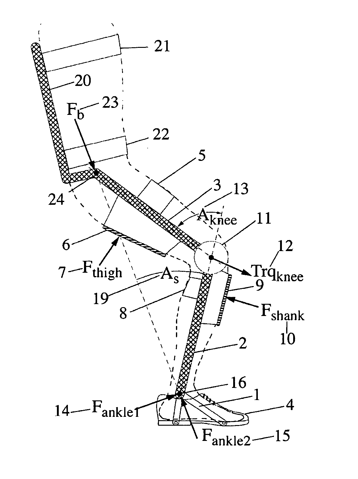
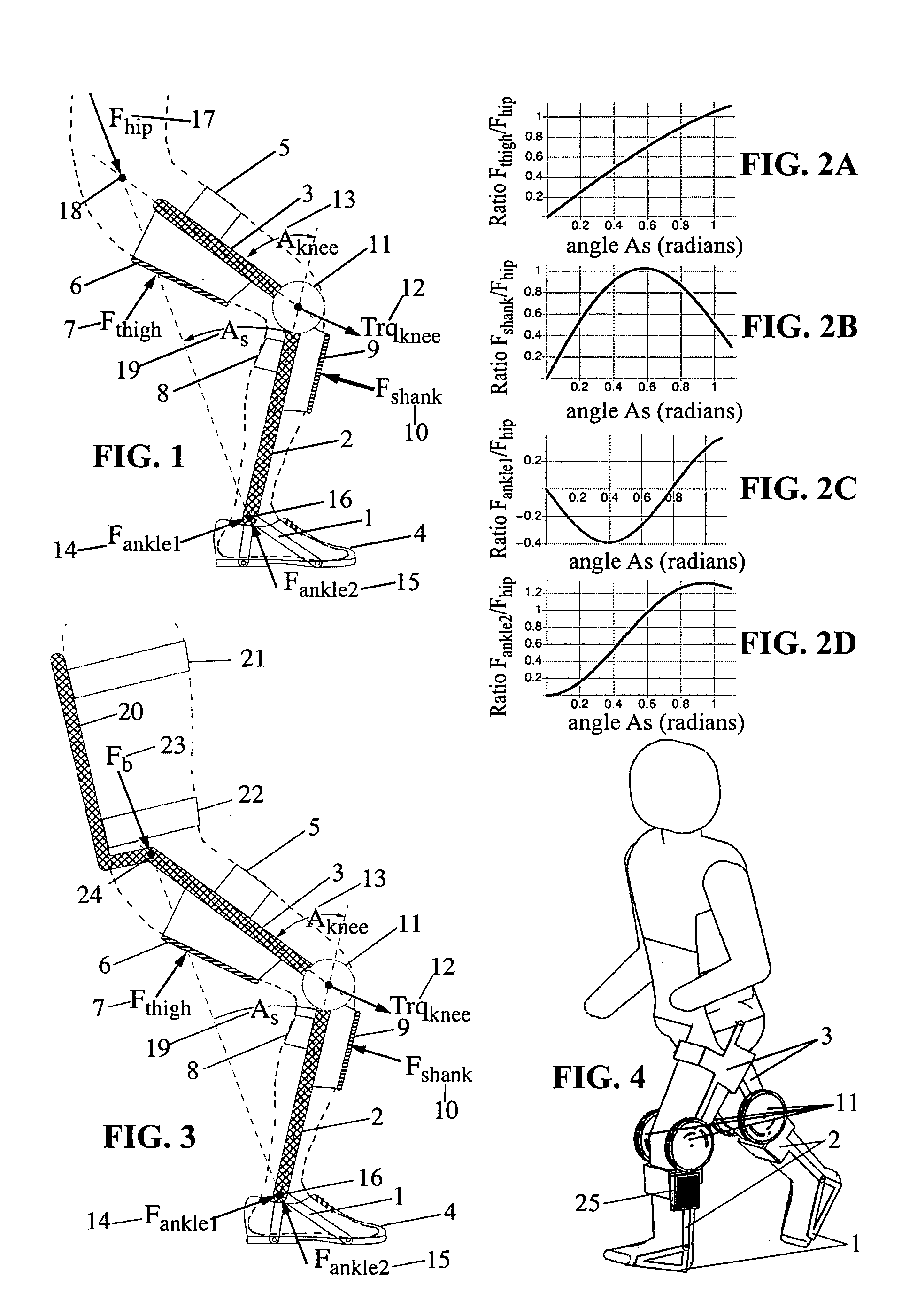
[0058] In the following discussion, the present invention shall be referenced as a leg brace or brace. When a wearer of the present invention dons the brace, the Ground Reaction Force (GRF) is transferred to the wearer's hip socket via two parallel structures. One structure is the wearer's femur, tibia, and foot skeletal bones. The other structure is the brace's thigh, shank, and shoe frames.

[0059] One embodiment of the invention addresses the problem of supporting the torso weight, supporting the weight of a carried load, and / or supporting the weight of an attached mass while standing, walking or running on any terrain. In addition to supporting the torso / carried load / attached mass weight, an embodiment of the invention also extracts and stores energy produced by the torso and / or carried load and / or attached mass during the period when the distance from a hip socket to an ankle is decreasing and then releases ...


PUM


Abstract

Embodiments of the invention relate to walking/running braces and to devices for enhancing locomotion, specifically human bipedal locomotion. More particularly, it relates to a controlled mechanical device which provides support of the torso via the hip sockets, reduces the metabolic energy associated with walking/running and reduces the incidence of falls caused by insufficient leg thrust. Embodiments of the invention also relates to reducing the strain and metabolic energy consumption associated with walking/running with a heavy backpack or other significant carried load.

Description

RELATED APPLICATION [0001] This application claims the benefit of U.S. Provisional Application No. 60 / 568,773, filed on May 6, 2004, the entire teachings of which are herein incorporated by reference.BACKGROUND OF THE INVENTION [0002] Ground Reaction Force (GRF) is defined as a force vector applied by the ground to a person at a point on a person's footprint called the Center of Pressure (COP). The GRF direction can be modeled by a force vector colinear with a line connecting ankle and hip. Neglecting air friction, the average horizontal component of the GRF must exactly equal zero for a person walking / running at constant average velocity regardless of ground slope. If this were not the case, then a person's torso would increase or decrease its average horizontal velocity. Similarly, the average vertical component of the GRF must be exactly equal to body weight regardless of the ground slope. If this were not the case, then the average distance from the torso to the ground would inc...

Claims


Application Information

Patent Timeline
Patent Type & Authority Applications(United States)
IPC IPC(8): A61F5/00A61F5/01A63B25/10
CPCA61F5/0102B25J9/0006A61F2005/0179A61F5/0125
Inventor CARVEY, MATTHEW R.CARVEY, ANDREW W.CARVEY, PHILIP P.HOWARD, NICHOLAS S.
Owner CARVEY MATTHEW R
Why Eureka
Try Eureka