Method and device for determining the position of a knee-joint endoprosthesis

Inactive Publication Date: 2005-11-10
AESCULAP AG
View PDF5 Cites 111 Cited by
  • Summary
  • Abstract
  • Description
  • Claims
  • Application Information

AI Technical Summary

Benefits of technology

[0021] The said variations may be performed individually or in combination, and it is clear that each of these changes to the position of the femoral part leads to a changed kinematic behavior of the knee joint. The described simulation of this movement obtained by the calculation of the respectively corresponding virtual relative positions of the femur and the tibia allow the surgeon to establish the consequences of a change to the position in each case by comparison of the virtual relative positions with the spread position in the straightened and bent knee and to keep varying the assumed position until on the one hand the desired coincidence with the spread position is achieved as well as possible and on the other hand a possibly desired correction, for example a varus-valgus correction, is achieved.
[0023] It is advantageous if, in the determination of the spread position, the gap between the femur and the tibial head is widened to the maximum extent. The system of ligaments becomes increasingly stiffer during the widening and, once extended by a certain amount, is virtually unable to extend any further, i.e. the distraction reaches saturation. The achievable extension in this range is relatively independent of the extending force expended, and for this reason it is advantageous to distract into this range; this produces results which can be reproduced well.
[0024] During the bending movement of the knee and also when the distraction appliance is engaged, the actual gap between the sliding surfaces of the femur and the tibial head can only be accurately determined from the monitoring of the position of the femur and the tibia if geometrical data on the shape of the femur and the tibia are additionally available. It is therefore envisaged according to a further development of the invention that, to determine the size of the gap between the femur and the tibia, the contour of the proximal tibial head and the contour of the distal femur are determined by the engagement of at least one navigated engaging element on these contours. This is a technique known per se for contour determination; the engagement of a navigated engaging element allows the navigation system to localize accurately the point of engagement or the line of engagement by the respective position of the engaging element in relation to the femur and the tibia, and from this to calculate geometrical data for the overall contour of the tibial head and of the femur.
[0034] It is also advantageous if the data processing system displays on the display the position of the femoral part assumed for the determination of various virtual relative positions in relation to geometrical data of the femur.

Problems solved by technology

This method is extremely laborious and entails the risk that, because of measuring errors, the desired tensioning conditions are not achieved after all once the operation has been carried out; this can have the effect that the surfaces of the joint are tensioned too little, or else too much, with respect to one another after the operation.

Method used


Image

  • Method and device for determining the position of a knee-joint endoprosthesis
  • Method and device for determining the position of a knee-joint endoprosthesis
  • Method and device for determining the position of a knee-joint endoprosthesis

Examples


Embodiment Construction

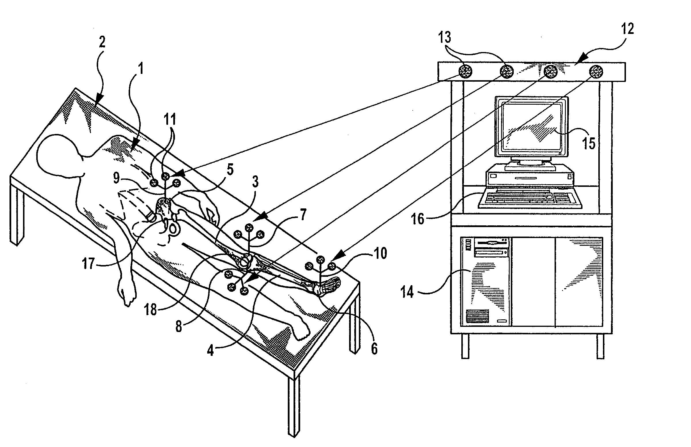
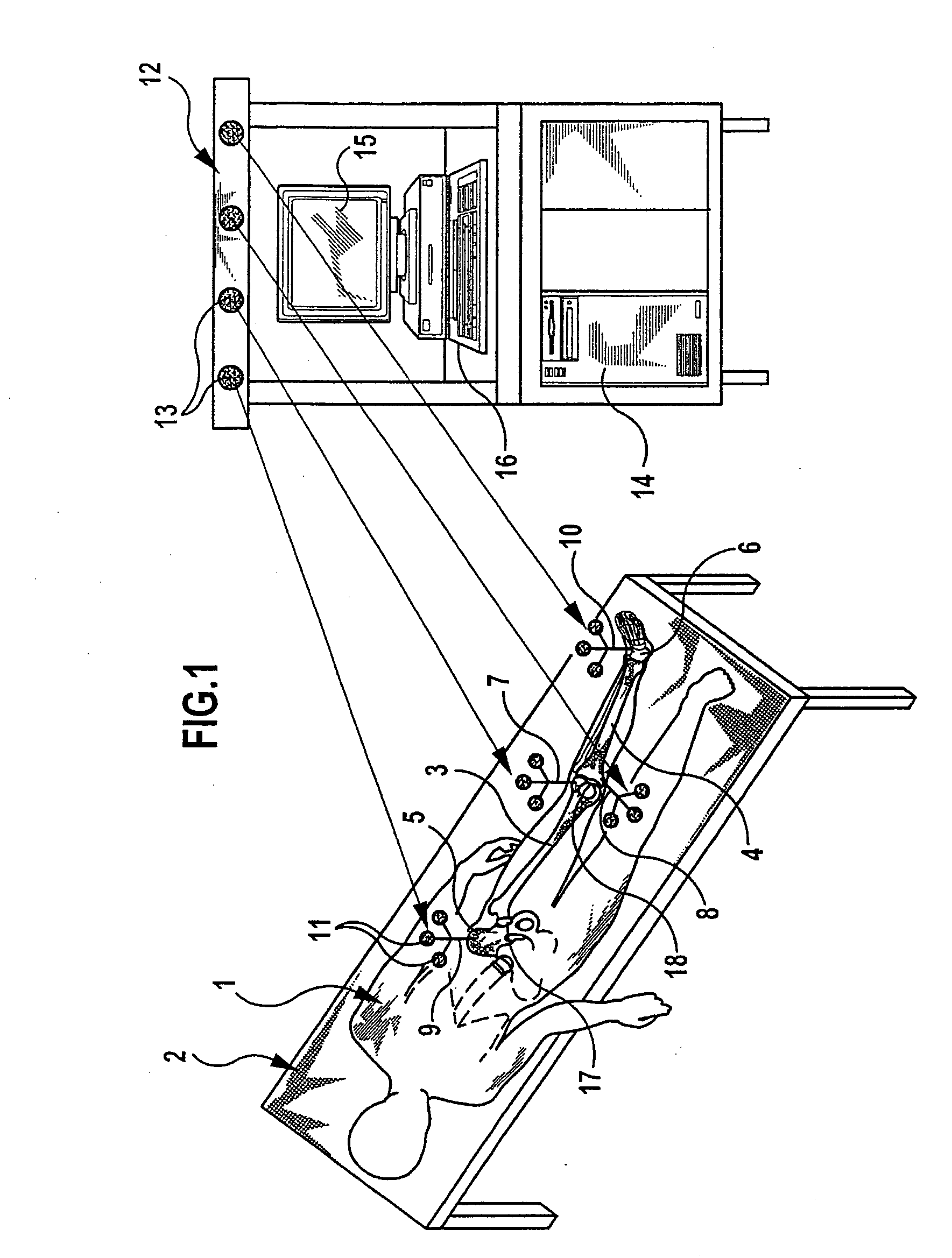
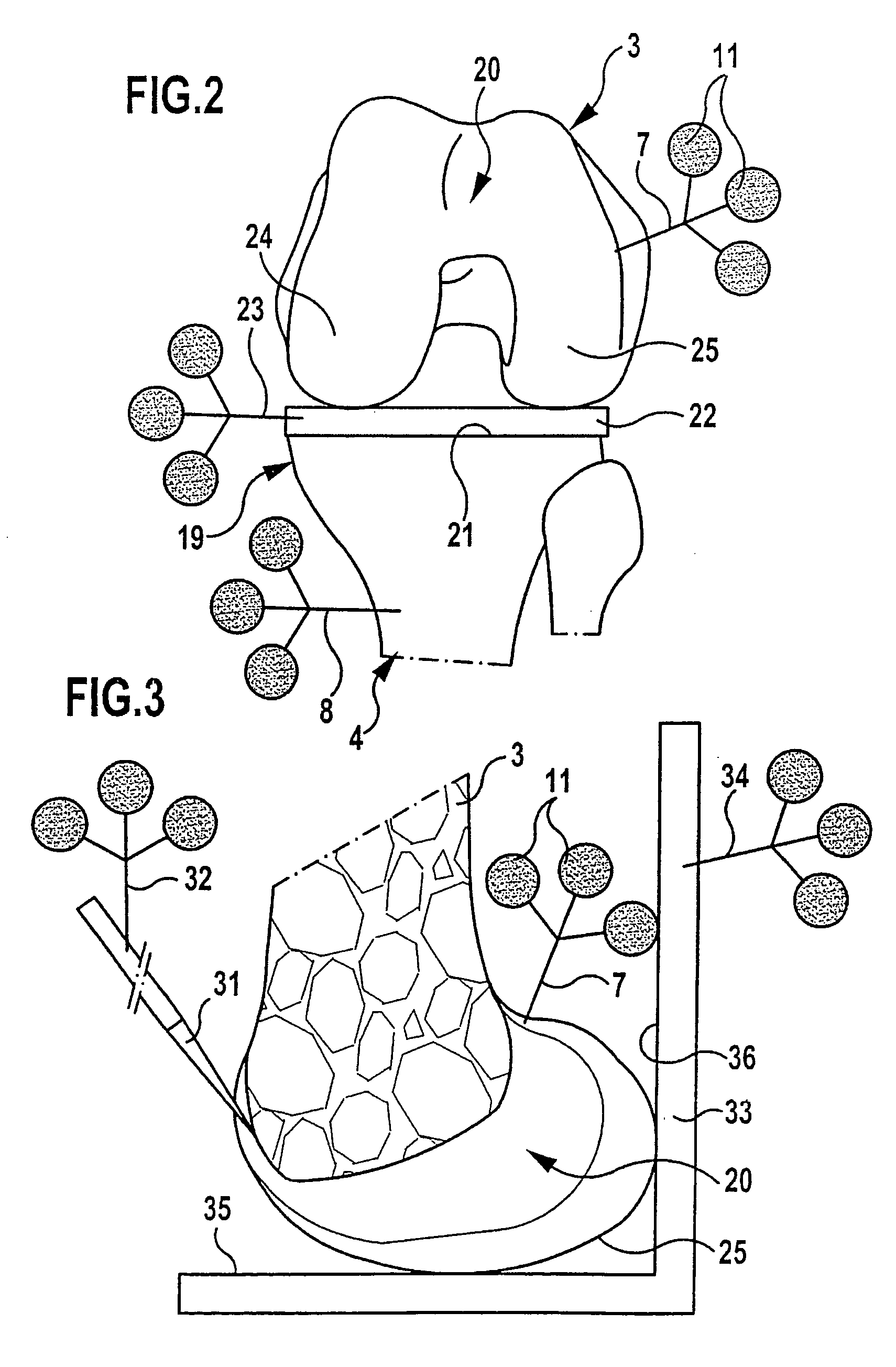
[0054] To replace a knee joint by a knee-joint endoprosthesis, the patient 1 is placed on an operating table 2, and the knee joint is opened up in a way known per se. Marking elements 7, 8, 9 and 10 are rigidly fixed at least to the femur 3 and to the tibia 4, and preferably also to the hip bone 5 and to the foot 6 of the patient, for example by screwing in a bone screw. Each of these marking elements carries three spaced-apart emitters 11, which may be active radiation transmitters for ultrasound radiation, infrared radiation or similar radiation, or else passive reflection elements for such a radiation, which then reflect, and thereby emit, radiation impinging on them. These marking elements operate together with a navigation system 12 with a number of radiation receivers 13, which establishes the spatial position and orientation of the marking elements and feeds data corresponding to this position to a data processing system 14. The data processing system 14 is equipped with a di...


PUM


Abstract

To be able to determine the insertion position of the parts of an artificial knee joint without changing the original knee joint, a method is proposed for determining the position of the tibial part and / or the femoral part of a knee-joint endoprosthesis in relation to the proximal tibial head or to the distal femur in which the position of the femur and of the tibia are monitored by means of a navigation system, in which the distal femur and the proximal tibial head are laterally and medially displaced with a defined force into a spread position by means of a distraction appliance when the knee is straightened and bent, and the relative positions of the femur and the tibia, and consequently the size of the gap between the femur and the tibia, are thereby respectively determined, in which various virtual relative positions of the femur and the tibia are calculated according to geometrical data of the knee-joint endoprosthesis and to different assumed positions of the tibial part on the tibia and / or of the femoral part on the femur when the knee is straightened and bent, and in which an assumed position in which the virtual relative position of the femur and the tibia when the knee is straightened and bent differs from the spread position in a specified manner is determined as a selected position.

Description

[0001] This application is a continuation of international application No. PCT / EP02 / 12319 filed on Nov. 5, 2002. [0002] The present disclosure relates to the subject matter disclosed in international application No. PCT / EP02 / 12319 of Nov. 5, 2002, which is incorporated herein by reference in its entirety and for all purposes.BACKGROUND OF THE INVENTION [0003] The invention relates to a method for determining the position of the tibial part and / or the femoral part of a knee-joint endoprosthesis in relation to the proximal tibial head or to the distal femur. Furthermore, the invention relates to a device for carrying out this method. [0004] In the implantation of a knee-joint endoprosthesis, endoprostheses which comprise two or three parts, for example a tibial part which can be fixed to the tibia, a femoral part which can be fixed to the femur, and an intermediate part, which is disposed between the femoral part and the tibial part, are often used. The tibial part and the femoral par...

Claims


Application Information

Patent Timeline
IPC IPC(8): A61B5/103A61B17/02A61B17/15A61B19/00A61F2/38A61F2/46G01S5/18G06T7/00
CPCA61B5/064A61B5/6878A61B5/4528A61B17/155A61B19/52A61B19/5244A61B2017/0268A61B2019/461A61B2019/467A61B2019/502A61B2019/505A61B2019/5255A61B2019/5268A61B2019/5272A61F2/38A61F2/3859A61F2/389A61F2/461A61F2/4657A61F2002/4632A61F2002/4658A61F2002/4668G01S5/186G06T7/0042G06T2207/30008A61B5/103A61B34/20A61B90/36A61B2034/102A61B2034/105A61B2034/2055A61B2034/2068A61B2034/2072A61B2090/061A61B2090/067G06T7/73
Inventor FRIEDRICH, DIRKLEITNER, FRANCOIS
Owner AESCULAP AG
Why Eureka
Try Eureka