
Bait stations

a technology of bait station and wick, which is applied in the field of bait station, can solve the problems of slow contact between wick and fluid, inconvenient construction of cages, and inability to provide optimally convenient means for liquid baits, and achieve the effect of inexpensive production

Inactive Publication Date: 2005-11-17
DUSTON TYLER D +5
View PDF28 Cites 33 Cited by
  • Summary
  • Abstract
  • Description
  • Claims
  • Application Information

AI Technical Summary

Benefits of technology

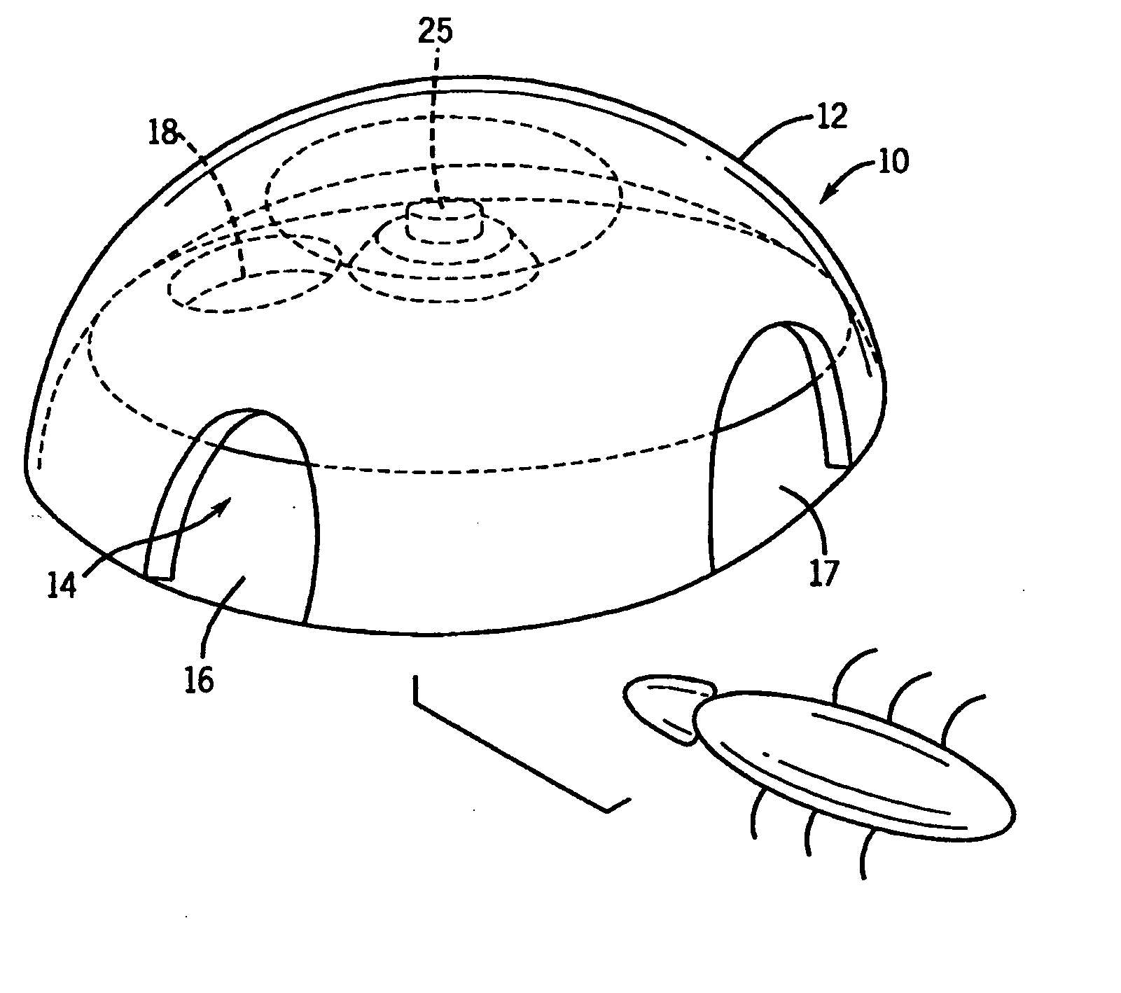
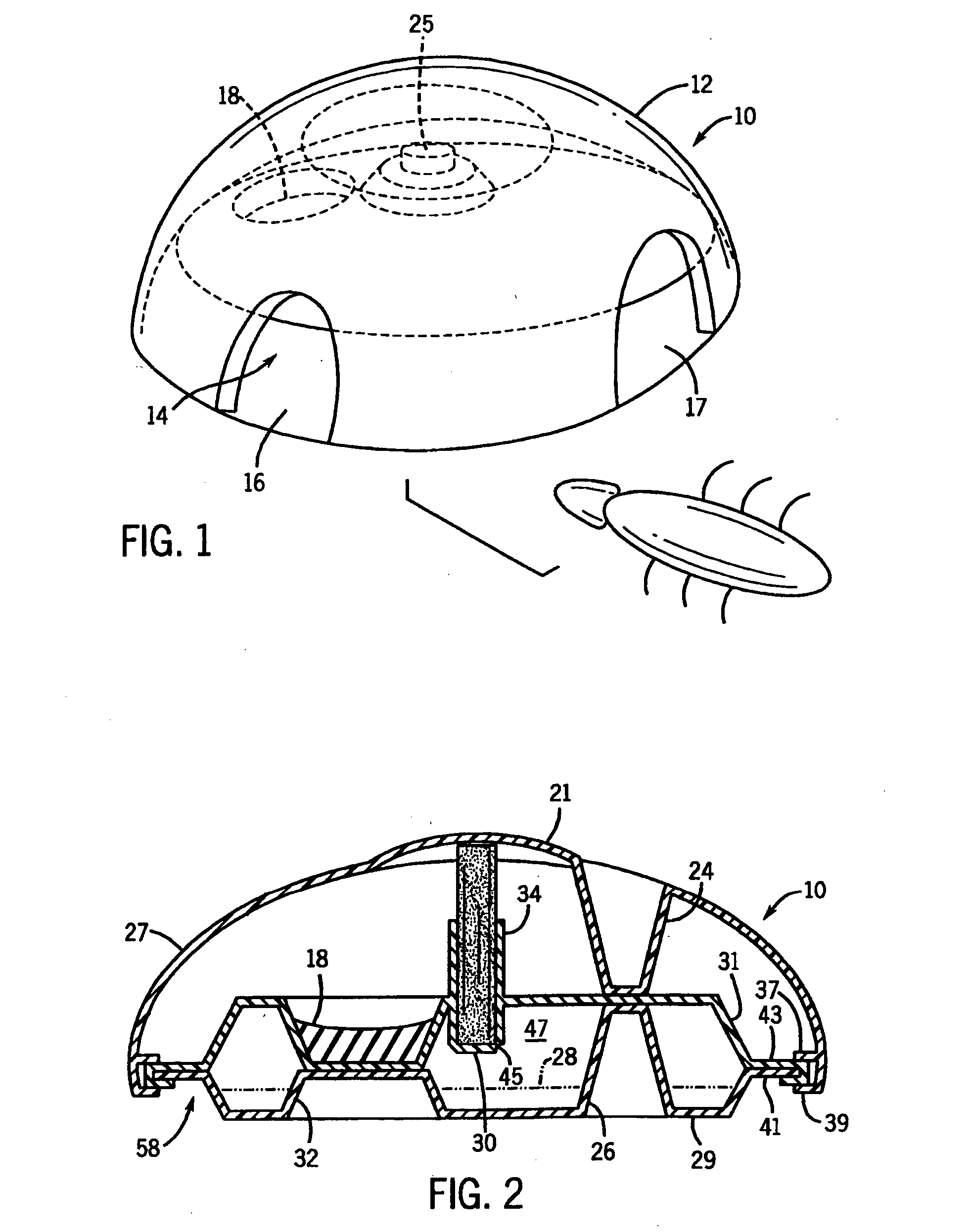
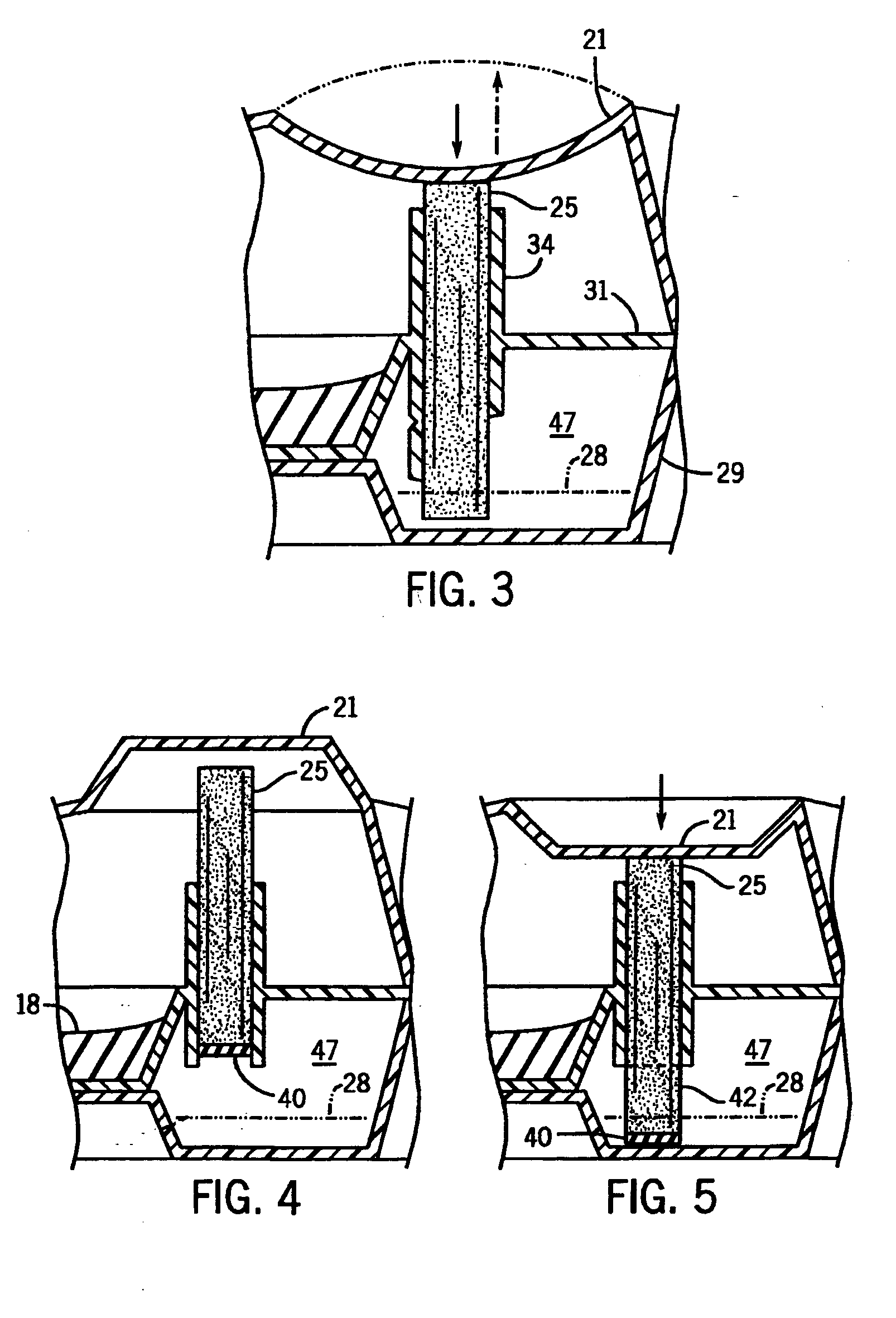
[0024] The structures of the present invention allow liquid bait to be safely stored during shipment and prior to use. A consumer can, in a highly intuitive manner, press down on the cover of the bait station to cause the wick to access the liquid bait. No complex cages are required to protect the wick. The wick either directly breaks the pierceable section, or directly carries a seal with no need for a pierceable section.

Problems solved by technology

However, currently available insect control devices that include liquid baits do not provide for an optimally convenient means for sealing the liquid during transport and storage, and then releasing the liquid for access by the pest when the insect bait station is placed into service.
However, the presence of the cage slows the contact of the wick and the fluid.
Further, the cage can be somewhat difficult to construct.

Method used


Image

  • Bait stations
  • Bait stations
  • Bait stations

Examples


third embodiment

[0032]FIG. 6 is a view similar to FIG. 4 but of a third embodiment having a support core extending down the center of the wick (the core then constituting a part of the wick);

fourth embodiment

[0033]FIG. 7 is a view similar to that of FIG. 6, but of a fourth embodiment having an angled lower wick end;

[0034]FIG. 8 is a further enlarged view of the FIG. 7 embodiment, albeit after activation, which may be constructed in one of two variants with respect to a venting system;

[0035]FIG. 9 is a first alternative sectional view taken along the line 9, 10-9, 10 of FIG. 8;

[0036]FIG. 10 is a second alternate sectional view taken along the line 9, 10-9, 10 of FIG. 8;

[0037]FIG. 11 is a perspective cutaway view of another alternate embodiment, showing a bait station having a housing that is generally pie wedge-shaped in top view;

[0038]FIG. 12 is a schematic view showing an alternative construction for the wick / piercing section interface;

[0039]FIG. 13 is a view similar to FIG. 12, but of another alternative construction for the wick / piercing section interface;

[0040]FIG. 14 is a view similar to FIG. 13, but of yet another alternative construction for the wick / piercing section interf...

second embodiment

[0056] Referring next to FIG. 4, in a second embodiment, the wick 25 is provided with a sealed end 40, while the sides of the wick 25 are not so sealed. The collar 34 for receiving the wick 25 can be provided with a thin, weak lower seal, or be left open to provide an access port to the reservoir 47, as the sealed end 40, when in the collar, limits liquid from entering the wick 25. It further limits evaporation through the wick 25.

[0057] When the activation area 21 of the cover is activated to force the wick 25 through the sealed bottom 30 or directly into the liquid container 47, the wick 25 absorbs liquid toxicant 28, e.g. through the unsealed sides 42. The cover 27 is constructed to be bi-stable, or to “oil can” such that the cover 27 becomes fixed in either of the inactive (FIG. 4) position or the active (FIG. 5) position.

[0058] Referring next to FIG. 6, the activation area 21 of the housing 12 is formed to include a downwardly-extending post or stiffener 23 which extends throu...


PUM


Abstract

A dual bait toxicant station includes a wick that can be moved to access a liquid reservoir, thereby activating the liquid feeding portion of the station. The wick can be selectively forced downward into the reservoir by activation of a lid which can have a bi-stable portion. The station may have a pie wedge-shaped top view, with multiple entrances along an arc portion of the station side.

Description

CROSS-REFERENCE TO RELATED APPLICATION [0001] This application claims the benefit of U.S. provisional application Ser. No. 60 / 569,906, filed on May 11, 2004 and entitled “Bait Stations”, which is hereby incorporated by reference in its entirety.STATEMENT REGARDING FEDERALLY SPONSORED RESEARCH OR DEVELOPMENT [0002] Not applicable DETAILED DESCRIPTION OF THE INVENTION [0003] The present invention relates to bait stations, preferably insecticidal bait stations, for the control of various pests such as cockroaches and ants. [0004] A variety of devices for holding poisonous bait to control crawling pests are known. These range from simple cardboard tubes open at both ends with a toxic bait glued inside, to more elaborate structures that have a centrally enclosed bait accessible by peripheral openings. Some of these devices are configured to hold a solid bait / toxicant preparation. “Solid” in this context means a non-pourable substance such as pastes, highly viscous gels, firm solids, and ...

Claims


Application Information

Patent Timeline
Patent Type & Authority Applications(United States)
IPC IPC(8): A01M1/20A01M25/00
CPCA01M1/2005A01M2200/011A01M25/004A01M1/2011
Inventor DUSTON, TYLER D.MINEAU, STEVEN B.MADALA, WILLIAM G.NICKEL, DIRK K.MEIER, MAUDE CHRISTIANSCHUMACHER, DONALD J.
Owner DUSTON TYLER D
Learn More