Haptic mechanism

a technology of force feedback and haptic mechanism, which is applied in the direction of mechanical control devices, limiting/preventing/returning movement of parts, control members, etc., can solve the problems of kinematic solution, algorithm which relates the position of the central joint to the angle at the base of each branch, and is generally more complex than that of a serial structure, so as to achieve the effect of being easily computabl

Inactive Publication Date: 2005-11-17
MPB TECH
View PDF18 Cites 49 Cited by
  • Summary
  • Abstract
  • Description
  • Claims
  • Application Information

AI Technical Summary

Benefits of technology

[0015] It is therefore an aim of the present invention to provide an improved hand controller allowing at least three-degree of freedom control.
[0016] It is also an aim of the present invention to provide a balanced hand controller able to hold a current position without assistance.
[0017] It is a further aim of the present invention to provide a hand controller with a compact geometry having a readily computable forward kinematic model.
[0023] The second and fourth links of each branch may have extensions outside the four-bar that hold counterweights, so that the payload and the links comprising the four-bar are balanced in the presence of gravity. Heavy counterweights are used near the axis of movement of the base, in order to minimize inertia.

Problems solved by technology

Moreover, all joints must be actuated, so either the weight of the joint motors is added to the weight of the links, or the mechanism is made more complex by the use of tendons or other means of transmitting torque to the joints from motors at the base.
Moreover, the kinematic solution, the algorithm which relates the position of the central joint to the angles at the base of each branch, is generally more complex than that of a serial structure.
However, this mechanism does not employ a balanced design, so its load capability is limited since the motors have to counteract significant gravitational forces to hold a given position.

Method used


Image

  • Haptic mechanism
  • Haptic mechanism
  • Haptic mechanism

Examples


Embodiment Construction

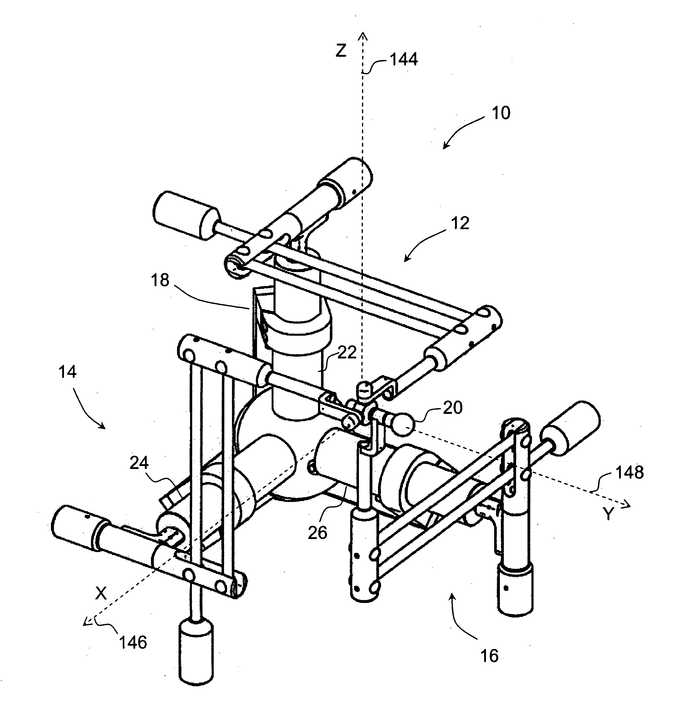
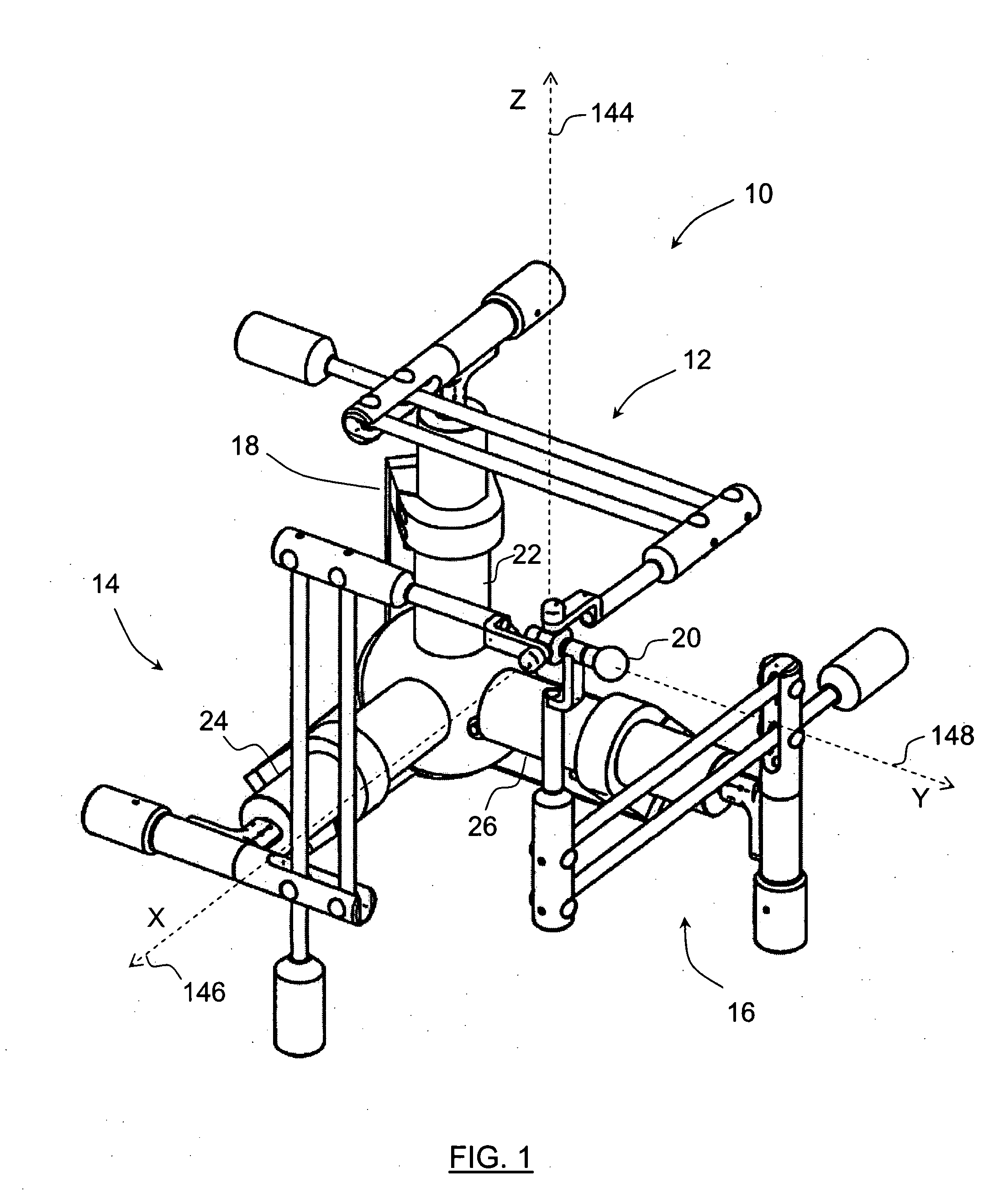
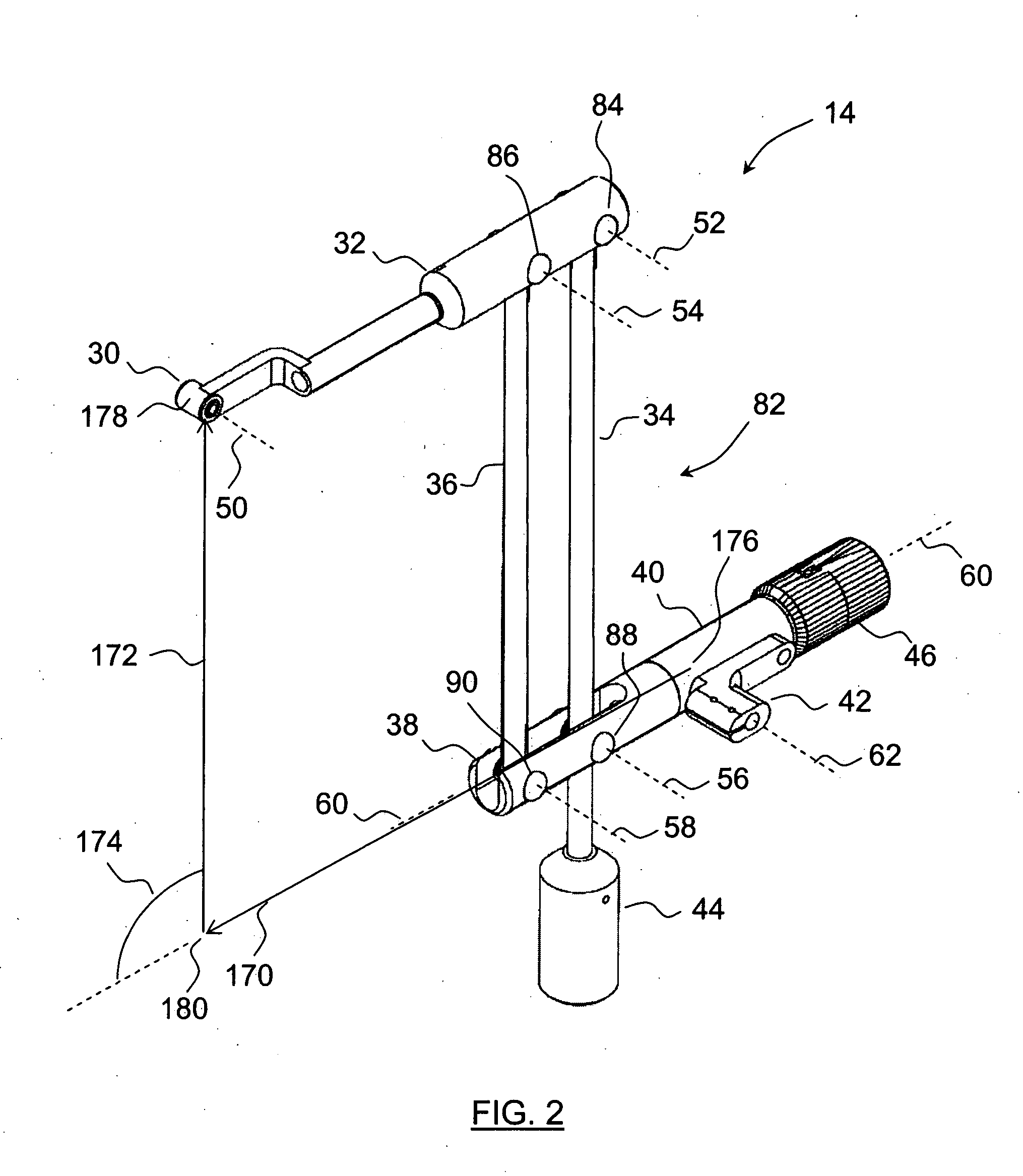
[0033] The present invention falls under the class of hybrid controllers, with a parallel mechanism supporting a serial handle mechanism. The serial handle mechanism may include motors which are generally lightweight. The controller has a balanced design, which permits the motors to apply all their power to the handle mechanism, rather than consuming energy to overcome an unbalanced gravitational load. The present invention makes use of an arrangement of the links that forms a cube in its home position. It therefore has the advantage of being amenable to a relatively simple kinematic approximate solution for three-degree of freedom control.

[0034] The mechanism of the present invention in connection with a computer allows for a user to move the handle mechanism to activate, for example, a virtual probe in a synchronous motion. The mechanism can produce a feedback force on the handle mechanism to be reflected to the user's hand when the virtual probe comes in contact with an obstacle...


PUM


Abstract

The present invention provides a parallel mechanism comprising a base, three rotary motors fixed on the base, each of the rotary motors having a rotating shaft, three branches, each of the branches having a first end and a second end, the first end of each of the branches being connected to the rotating shaft of a different one of the rotary motors, a central coupler connected to the second end of all of the branches, the branches constraining the central coupler to be movable along at least three degrees of freedom as a function of actuation from any one of the three rotary motors, and at least one counterweight for each of the branches to balance the same about at least the rotating shaft of the corresponding one of the rotary motors such that the central coupler holds a current position and orientation without assistance from the rotary motors.

Description

BACKGROUND OF THE INVENTION [0001] 1. Field of the Invention [0002] The present invention relates to force feedback hand controllers, particularly to three to six degree of freedom hand controllers with rotational handles. [0003] 2. Background Art [0004] Force-reflecting master hand controllers fall under two main categories, namely serial mechanisms and parallel mechanisms, and can also be a combination of both in the case of hybrid constructions. [0005] Serial mechanisms or linkages comprise a series of generally rigid links that are joined end-to-end in series. They form a structure analogous to a human arm, with a shoulder supporting an upper arm, which supports a lower arm, which in turn supports a hand. The hand is termed a distal stage, and supports a handle that the user may grasp to move the mechanism. The shoulder is normally mounted to a fixed base. Motors connected to the joints in the linkages serve to apply force and / or torque to the handle. [0006] Serial mechanisms of...

Claims


Application Information

Patent Timeline
Patent Type & Authority Applications(United States)
IPC IPC(8): B25J13/02B25J17/02G05G1/04G05G5/03G05G5/26G05G9/047
CPCB25J13/02B25J17/0266Y10T74/20201G05G2009/04707G05G2009/04766G05G9/047B25J13/025
Inventor DEMERS, JEAN-GUY
Owner MPB TECH
Why Eureka
Try Eureka