
Food fryer

a technology for fryers and food, which is applied in the field of food fryers, can solve the problems of not being able to handle the conventional food fryer, and achieve the effect of reducing the assembly work and the factory cost of the food fryer

Active Publication Date: 2005-11-17
SATO
View PDF3 Cites 29 Cited by
  • Summary
  • Abstract
  • Description
  • Claims
  • Application Information

AI Technical Summary

Benefits of technology

[0022] In this situation, cleaning work for inside of the food fryer, which is the oil layer area and the water layer area outside the oil storage tank, can commence efficiently, safely and immediately without time elapse for cooling of the used oil.
[0023] After cleaning up the food fryer and closing the water discharge cock of the water layer area, water is newly poured into the food fryer. The water increases in the water layer area of the food fryer and eventually flows into the oil storage tank from its opening, and thereby the oil in the oil storage tank accordingly moves up to the oil layer area due to the difference in gravity between the oil and the water. In this way, the oil is put back to the oil layer area with simple operation and can be used repeatedly over and over.
[0025] And having the opening without any cock at the upper position of the oil storage tank, this invention is effective in that number of components, assembling work thereof and factory expenses of the food fryer are respectively reduced, and in that the cleaning work next to the frying work in the food fryer is easy to be done.

Problems solved by technology

In this way, it is not easy to handle the conventional food fryer.

Method used


Image

  • Food fryer
  • Food fryer
  • Food fryer

Examples


Embodiment Construction

)

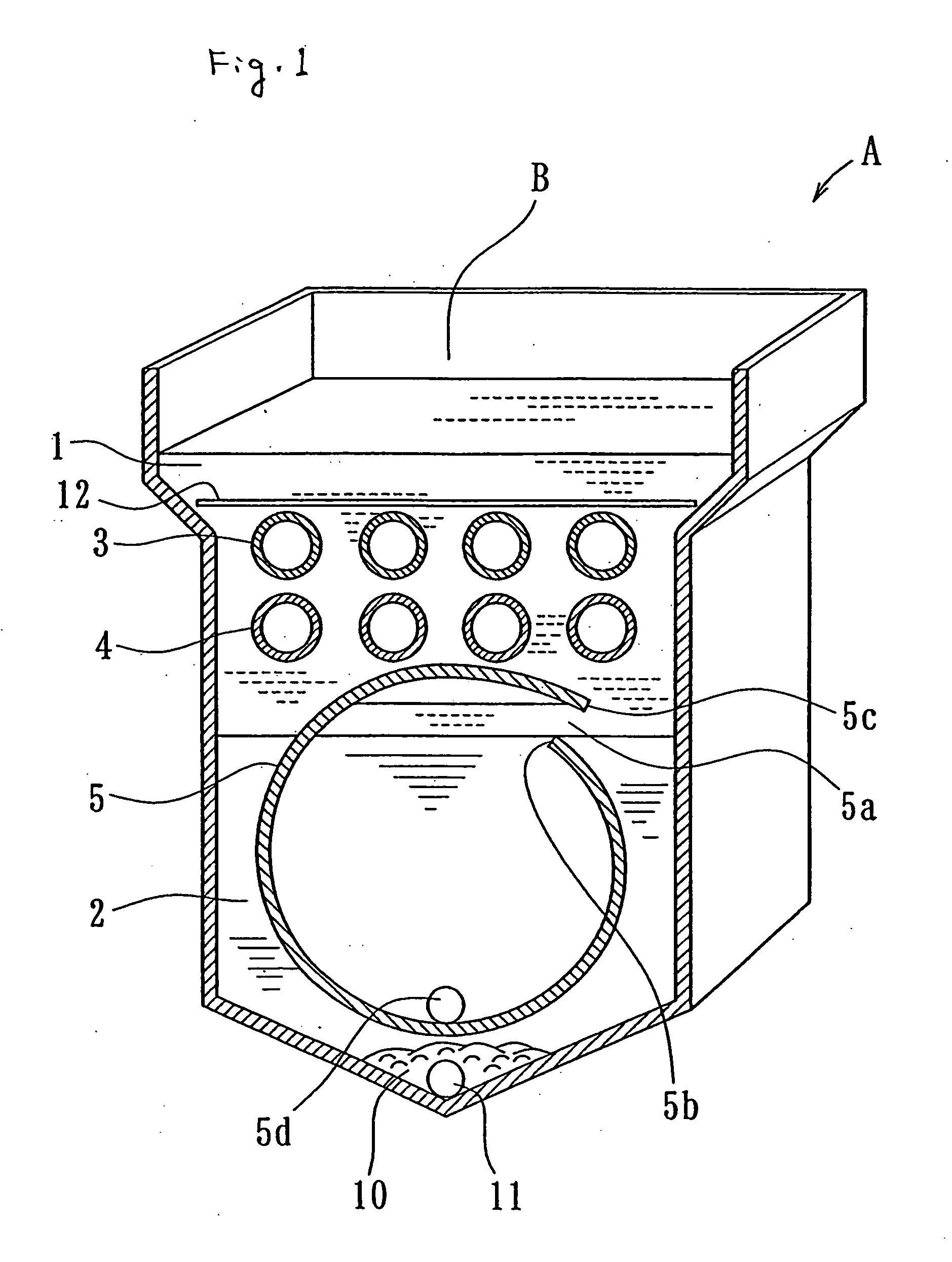
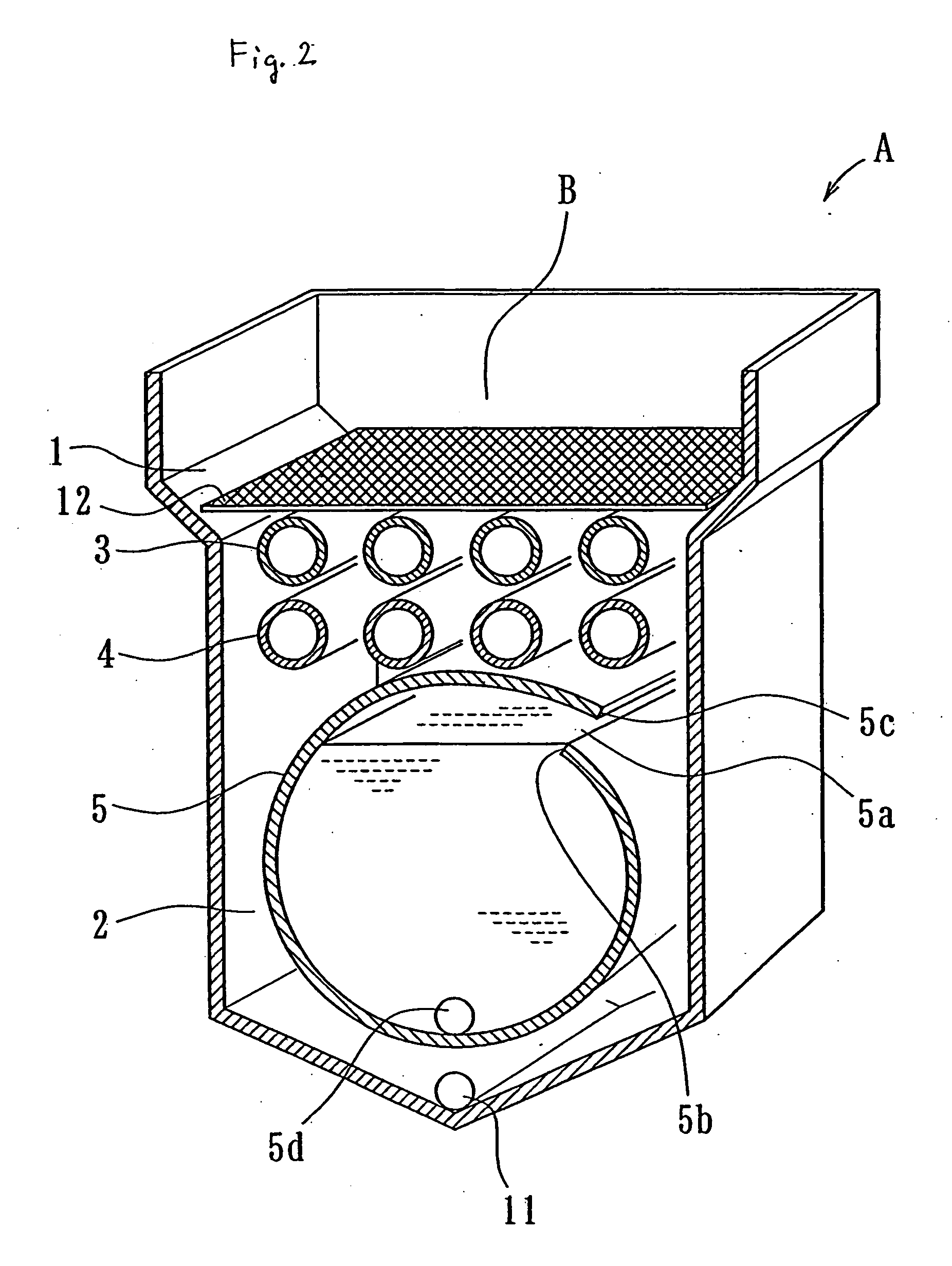
[0034] The invention is explained more in detail with reference to the attached figures from FIG. 1 to FIG. 6.

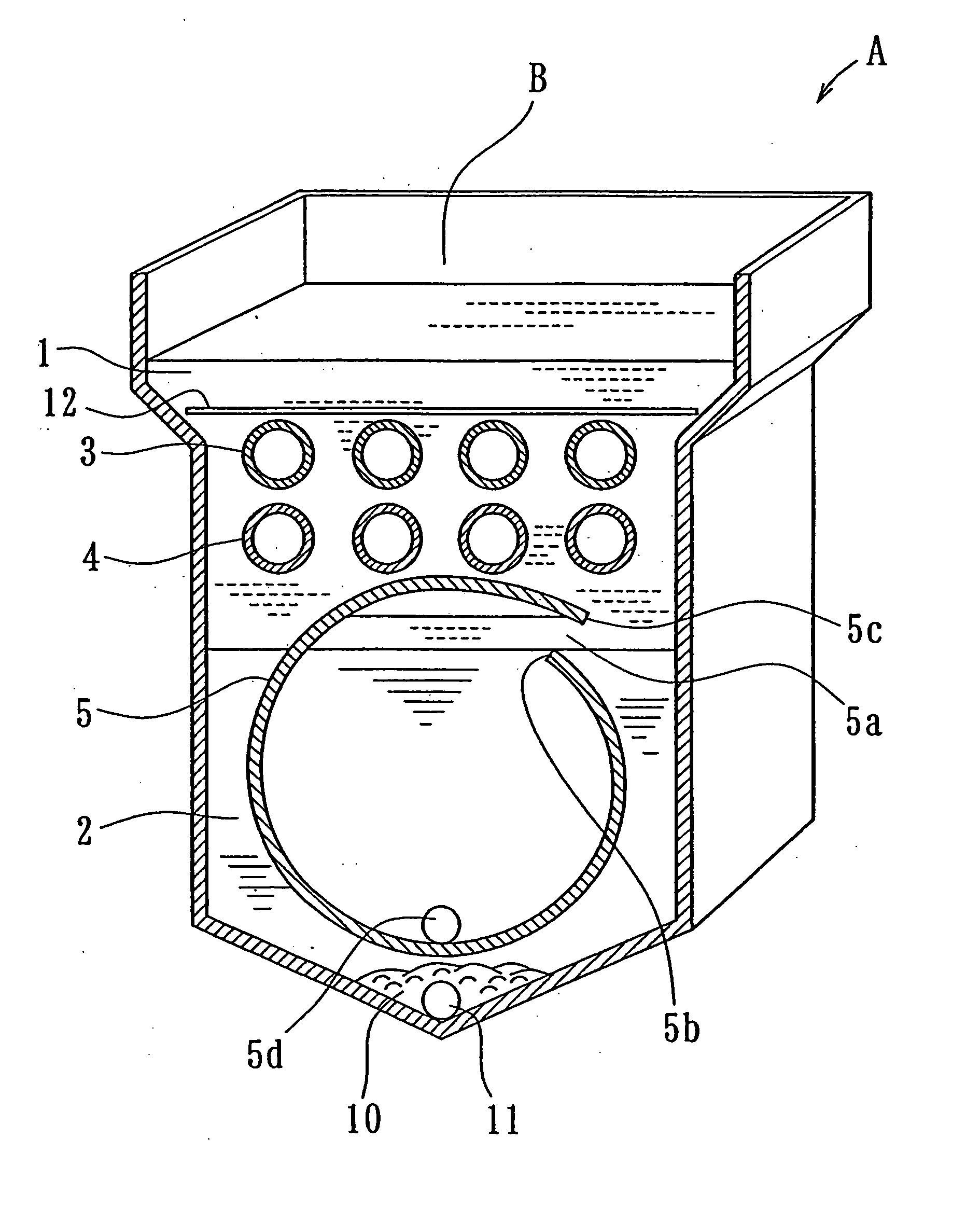
[0035] In these figures: [0036] A is a food fryer having a cylindrical oil storage tank with circular sectional view; [0037] B is a frying food tank of the food fryer A; [0038] C is another food fryer having a cylindrical oil storage tank with ellipsoid sectional view; [0039] D is a frying food tank of the food fryer C; [0040] E is another food fryer for household use; [0041] F is a frying food tank of the food fryer E; [0042] G is the other food fryer having a rectangular parallelepiped oil storage tank; [0043] H is a frying food tank of the food fryer G; [0044]1 is an oil layer area; [0045]2 is a water layer area; [0046]3 is a heat source (heat pipe), 3′ is an electric heater as a heat source; [0047]4 is an air cooling tube; [0048]5 is a cylindrical oil storage tank, 5a is an opening formed on the upper side wall of the oil storage tank, 5b is a lower end of the opening,...


PUM


Abstract

A food fryer allowing a fried food tank to be safely and efficiently cleaned, wherein an opening part (5a) is formed in the side upper part of an oil storage tank (5) so that an upper end part (5c) covers a lower end part (5b) a cock (5d) is installed at the bottom part of the tank, the opening part (5a) is positioned near a boundary between an oil tank area (1) and a water tank area (2), a cover part is not provided for the opening part, after a food frying operation is completed, first oil in the oil tank area (1) is stored in the oil storage tank (5) through the opening part (5a) by the opening and closing operation of the cock (5d) and then a cock (11) is opened to drain the oil from those portions other than the oil storage tank of the fried food tank (B), and the tank is cleaned, and when the next frying operation is started, the oil in the oil storage tank (5) is moved to the oil tank area (1) due to a difference in gravity between the oil and water by merely feeding the water into the fried food tank (B).

Description

TECHNOLOGY FIELD (FIELD OF THE INVENTION) [0001] This invention relates to a food fryer having a frying food tank which comprises a water layer area (a water tank area) and an oil layer area (an oil tank area) there on, in which bits of fried batter are coming down to the water layer area through the oil layer area, especially having an oil storage tank formed at a predetermined position of the water layer area. BACKGROUND ART (BACKGROUND OF THE INVENTION) [0002]FIG. 7 shows an external view structure of a conventional food fryer, and FIG. 8 shows a sectional view of an oil layer area and a water layer area in the conventional food fryer: [0003]1 is the oil layer area for storing food frying oil; 2 is the water layer area; 3 is a heat source such as a heating burner; 4 is an air cooling tube formed by a means such as welding on the outer wall of the oil layer area 1; 10 is bits of fried batter; 11 is a water discharge cock; 12 is a net; 14 is an oil discharge cock; 15 is an adjustin...

Claims


Application Information

Patent Timeline
Patent Type & Authority Applications(United States)
IPC IPC(8): A47J37/12
CPCA47J37/1285A47J37/1271A47J37/129
Inventor SATO, TADAYOSHI
Owner SATO
Learn More