Heat dissipation device having thermally conductive cover board

a heat dissipation device and thermally conductive technology, which is applied in the direction of semiconductor devices, cooling/ventilation/heating modifications, semiconductor/solid-state device details, etc., can solve the problems of system failure of the computer, insufficient heat dissipation device heat removal by the finned heat dissipation device to maintain the operation temperature of the cpu, and it is extremely difficult to install a large-sized heat dissipation device with larg

Inactive Publication Date: 2005-11-17
MITAC TECH CORP
View PDF12 Cites 13 Cited by
  • Summary
  • Abstract
  • Description
  • Claims
  • Application Information

AI Technical Summary

Benefits of technology

[0008] A primary objective of the present invention is to provide a heat dissipation device having enhanced heat transfer and thus heat removal rate without significant modification of an existing heat dissipation device.
[0009] Another objective of the present invention is to provide a heat dissipation device comprising a thermally conductive surface cover board to enhance heat removal rate of the heat dissipation device.
[0010] A further objective of the present invention is to provide a force-convection heat dissipation device that, besides primary heat transfer between a finned structure of the heat dissipation device and airflow induced by a fan, also performs secondary heat transfer between the heat dissipation device and airflow so as to enhance heat removal rate of the heat dissipation device.
[0011] To achieve the above objectives, in accordance with the present invention, there is provided a hea...

Problems solved by technology

Malfunctioning or improper operation of the CPU due to undesired high temperature usually results in system failure of the computer.
However, for such high-speed computers, heat removed from the CPU by the finned heat dissipation device is not sufficient to maintain the operation temperature of the CPU.
This is especially true for computers having small physical size, such as a notebook computer, which has an impact arrangement of electronic parts, making it ex...

Method used


Image

  • Heat dissipation device having thermally conductive cover board
  • Heat dissipation device having thermally conductive cover board
  • Heat dissipation device having thermally conductive cover board

Examples


Embodiment Construction

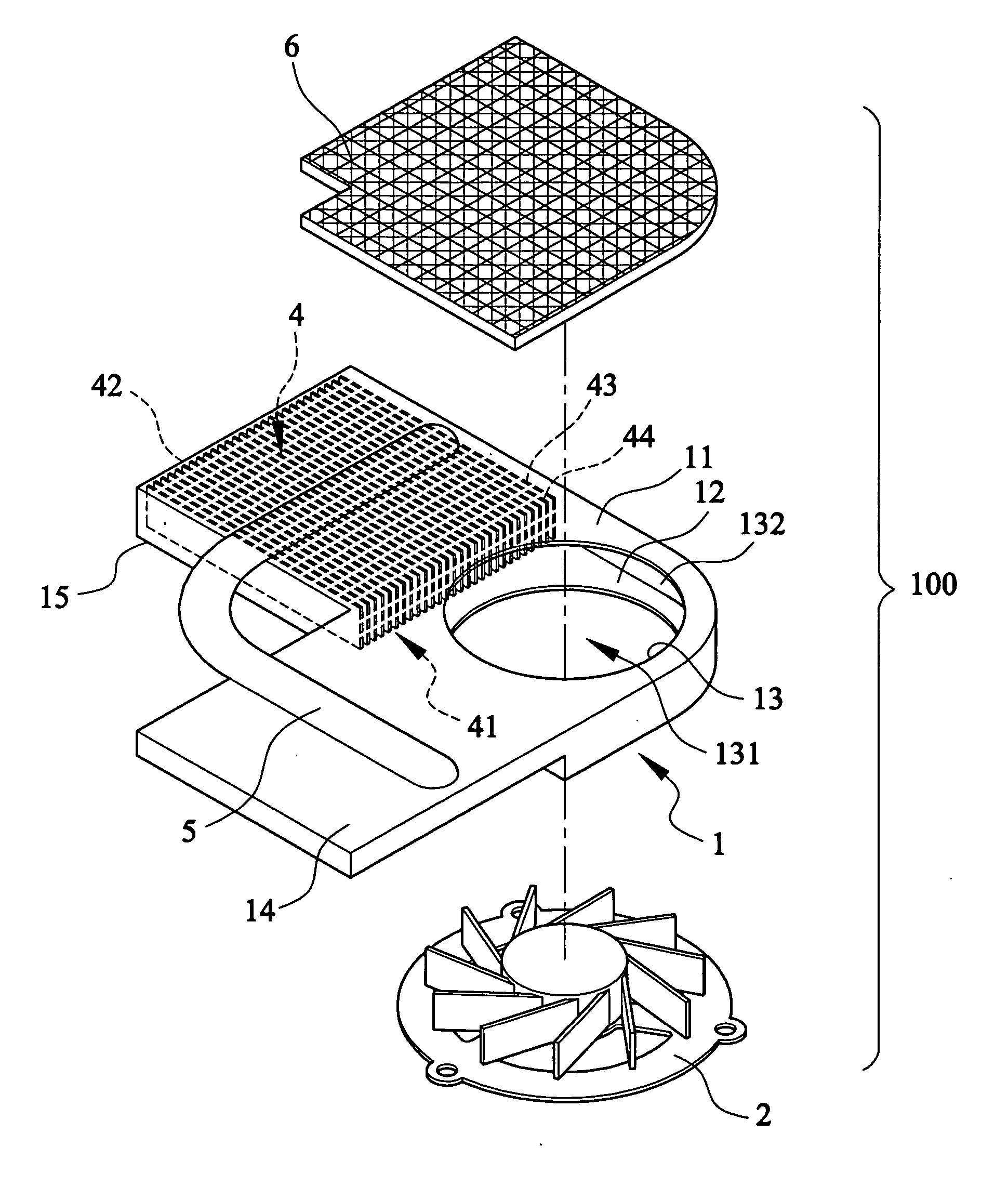
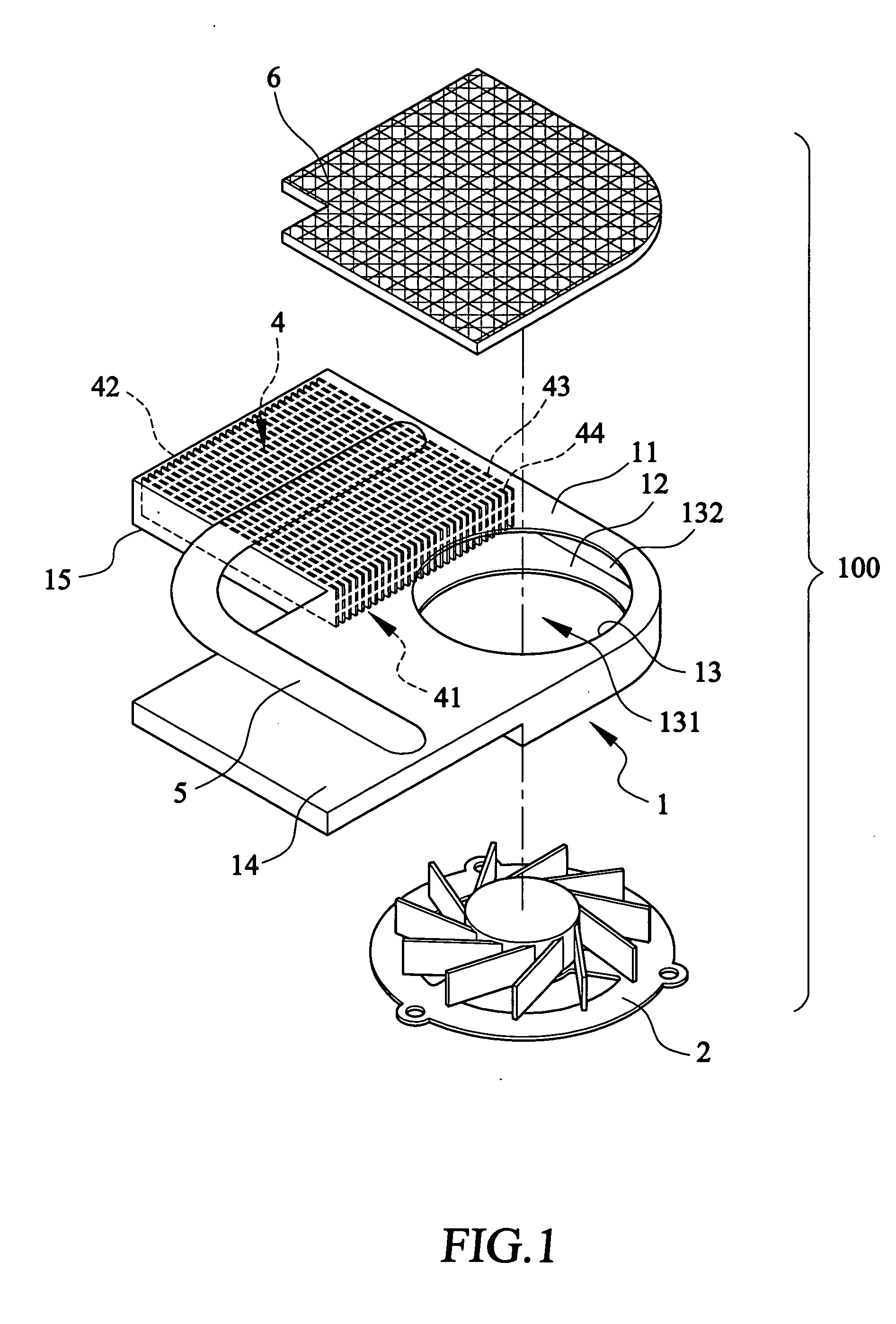
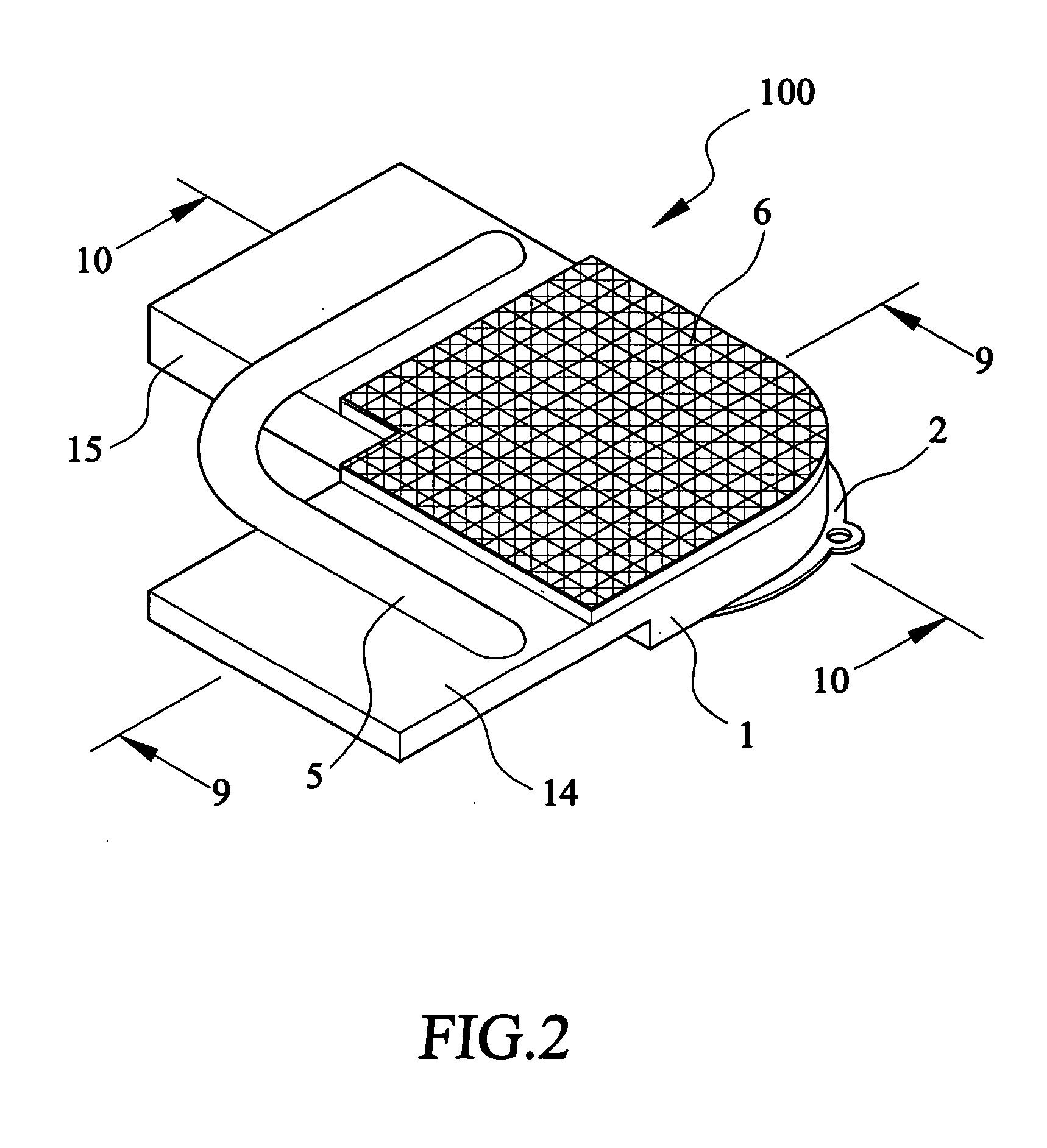
[0024] With reference to the drawings and in particular to FIGS. 1 and 2, a heat dissipation device constructed in accordance with the present invention, generally designated with reference numeral 100, comprises a casing 1, made of thermally conductive material, which is comprised of spaced and opposite upper and lower plates 11, 12 connected to each other by a sidewall (not labeled) to define a chamber inside the casing 1. Aligned holes are defined in the upper and lower plates 11, 12 to form a receptacle 13 for receiving and retaining a fan module 2. The hole defined in the upper plate 11 that constitutes in part the fan receptacle 13 serves an a first entrance or inlet 131 for air drawn into the chamber by the fan module 2. An opening 132 is defined in the sidewall functions as a second entrance or inlet for air drawn into the chamber by the fan module 2. Alternatively, the chamber may have an open sidewall to provide the second air entrance.

[0025] Also referring to FIG. 3, a d...


PUM


Abstract

A heat dissipation device includes a casing forming a receptacle for receiving and retaining a fan module and a finned structure that includes spaced fins to define channels through air flows for primary exchange of heat with the heat dissipation device. The heat dissipation device further includes a thermally conductive surface cover board that is mounted to the casing to at least partly cover an air entrance that is defined in the casing to allow air to be drawn into the casing by the fan module. The surface cover board defines air passages through which air is conducted into the casing. Heat is exchanged with the air when the airflow passes through the surface cover board. Thus, the heat dissipation device features twice heat exchange with airflow and thus enhanced heat removal rate by simply adding the surface cover board to the casing and without significant modification of the existing heat dissipation device.

Description

FIELD OF THE INVENTION [0001] The present invention relates generally to a heat dissipation device, and in particular to a heat dissipation device having a thermally conductive surface cover board to enhance heat removal rate. BACKGROUND OF THE INVENTION [0002] Integrated circuits (ICs) are commonly employed in various electrical / electronic devices. The ICs are often subject to constraint of temperature in order to maintain proper operation. In other words, heat generated by the ICs must be timely removed in order to maintain proper operation temperature of the ICs. A heat dissipation device is often employed to remove heat generated by the ICs. This is of vital importance for some ICs, such as a central processing unit (CPU) of a computer system, for the CPU is the core of operation of the computer system. Malfunctioning or improper operation of the CPU due to undesired high temperature usually results in system failure of the computer. A conventional heat dissipation device for th...

Claims


Application Information

Patent Timeline
IPC IPC(8): H01L23/36H05K7/20H01L23/427H01L23/467
CPCH01L23/427H01L23/467H01L2924/0002H01L2924/00
Inventor CHANG, JUEI-CHI
Owner MITAC TECH CORP
Why Eureka
Try Eureka