
Water treatment unit for bottle or pitcher

a water treatment unit and pitcher technology, applied in the field of water treatment units, can solve the problems of reducing the service life of carbon water treatment units, affecting the recovery of water, so as to achieve rapid venting of water bottles and recovery, the effect of convenient housing

Inactive Publication Date: 2005-11-17
CHAU YIU CHAU
View PDF43 Cites 44 Cited by
  • Summary
  • Abstract
  • Description
  • Claims
  • Application Information

AI Technical Summary

Benefits of technology

[0002] Carbon has been used extensively in water treatment for the purification of water. However, the growth of bacteria in the carbon is always a concern. Moreover, the presence of chlorine in the water shortens the life of the carbon.

Problems solved by technology

However, the growth of bacteria in the carbon is always a concern.
Moreover, the presence of chlorine in the water shortens the life of the carbon.
However, pretreatment of the water in a carbon water treatment unit employed in, for example a sport water bottle, is generally difficult due to the restrictions on size of the treatment unit and / or the low water pressures encountered in such units.
Size presents a problem simply due to the fact that it is difficult to provide multiple treatment chambers which are of a size to contain a sufficient amount of treatment medium in such relatively small units.
Water pressure presents a problem due to the fact that it may be difficult to force the water through the treatment medium which, for example, because of size restrictions presents a small cross sectional area resulting in greater pressure drops.
However, again due to the size restrictions encountered in a water treatment unit used in, for example a sport water bottle, such post treatment is difficult to achieve.
An additional problem is presented to the use of a water treatment unit in a sport water bottle because of the need to equalize the pressure in the bottle after treated water has been discharged from the bottle.
However, because the air must pass through the filter medium, its passage is slowed and recovery of the bottle is retarded.

Method used


Image

  • Water treatment unit for bottle or pitcher
  • Water treatment unit for bottle or pitcher
  • Water treatment unit for bottle or pitcher

Examples


Embodiment Construction

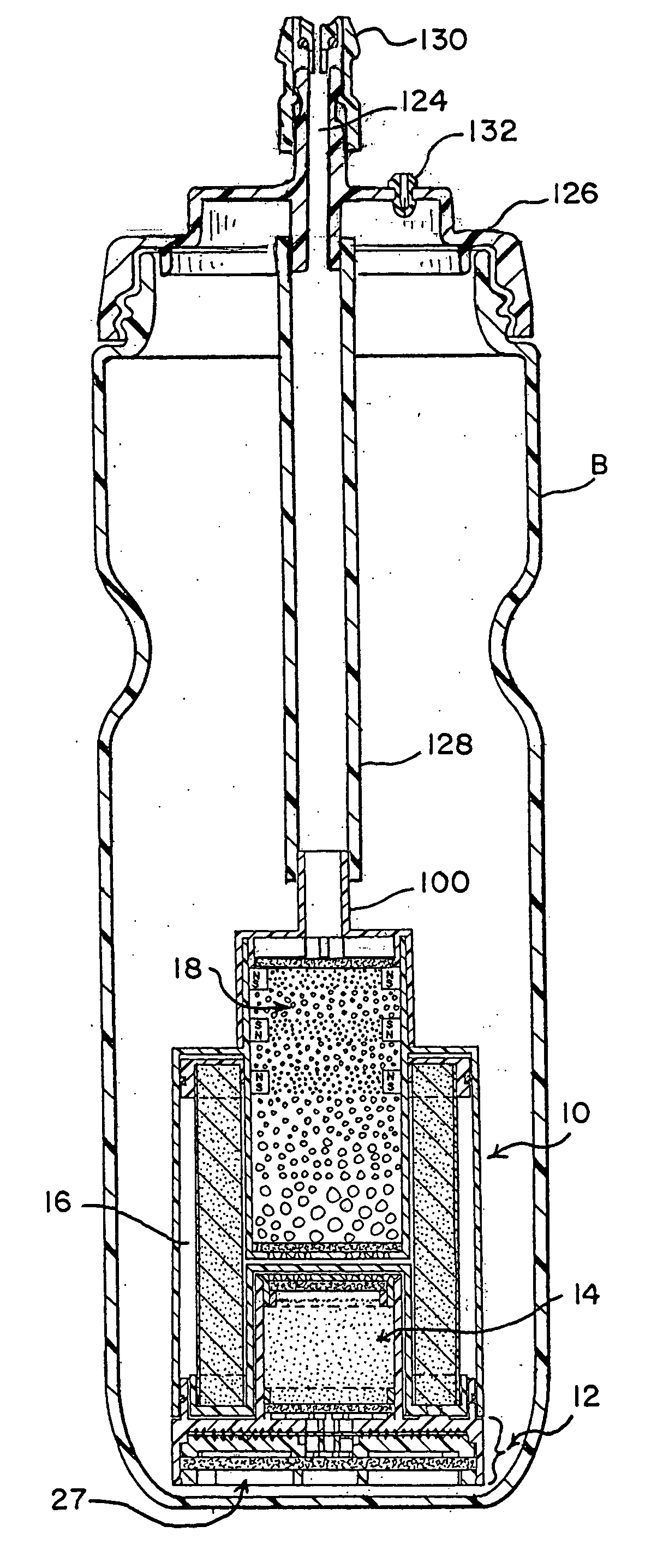
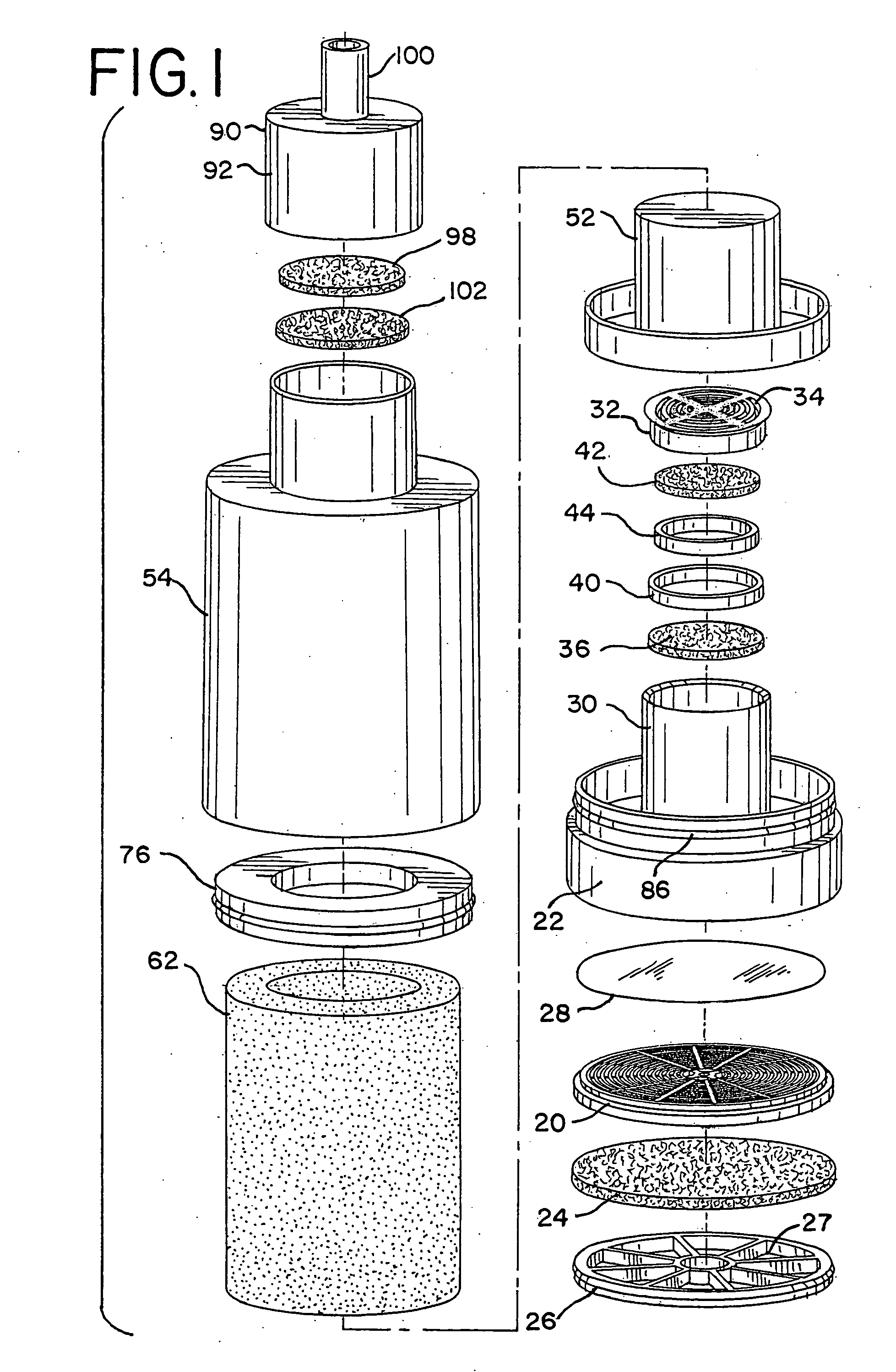
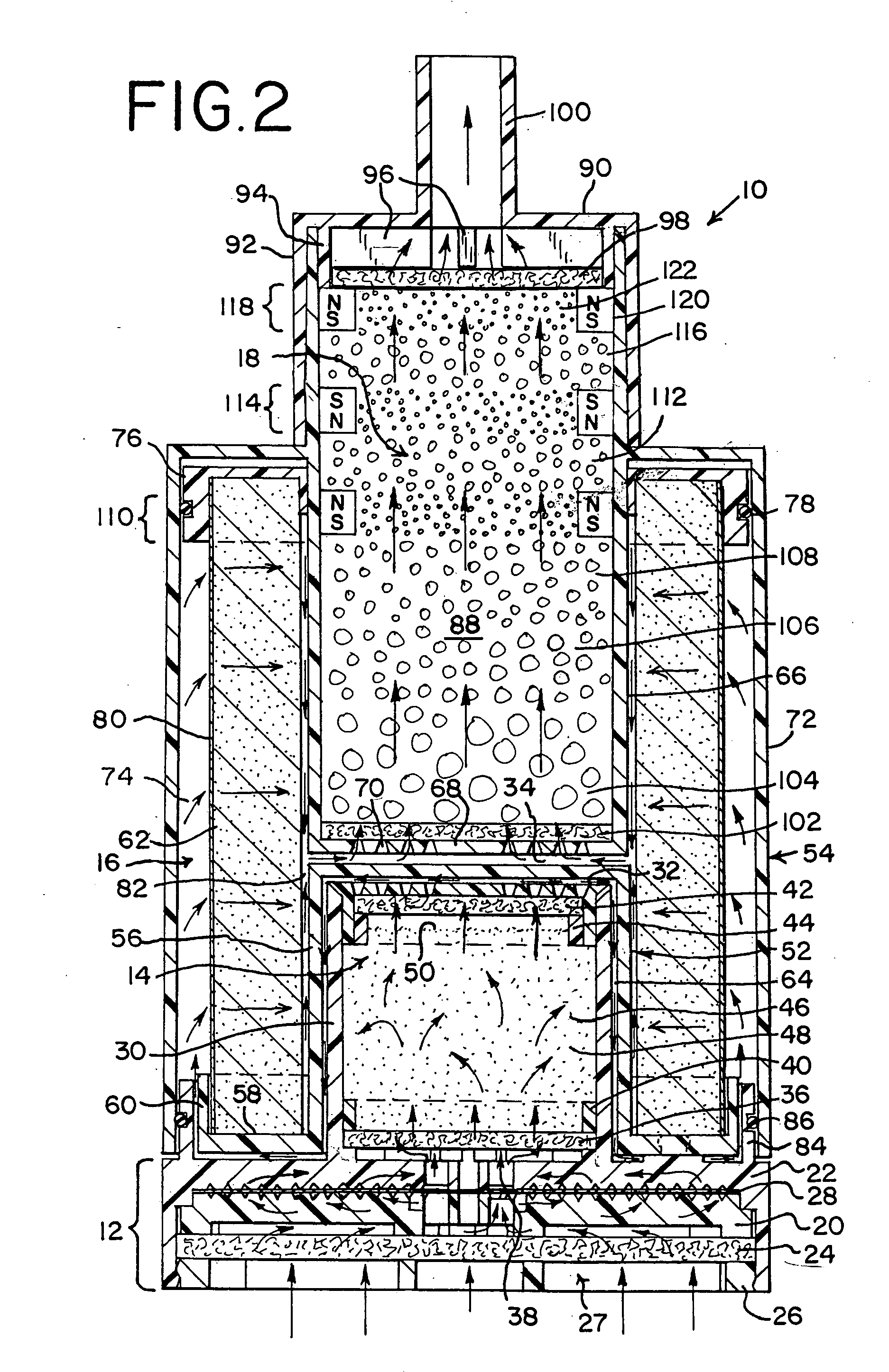
[0028] With particular reference to FIGS. 1-3, one preferred embodiment of water treatment unit 10 of the present invention is shown. The water treatment unit 10 in general comprises a prefilter section 12, a pretreatment section 14, a treatment section 16 and a post treatment section 18.

[0029] The prefilter section 12 comprises a filter holder 20 and base 22. A filter 24 is positioned upwardly as shown in FIG. 2 against the bottom side of the base 22, and a filter holder 26 having openings therethrough which define an inlet 27 to the unit 10 is positioned against the bottom side of the filter 24 to hold the filter 24 in place. The filter 24 preferably has a pore size of about 10 μm. The filter holder 26 may be held in place by a snap fit into the bottom of the prefilter section 12 as shown in FIG. 2.

[0030] A fine membrane filter film 28 is positioned on top of the filter holder 20 and beneath the base 22. Filter film 28 has the purpose of retaining extremely fine particulate cont...


PUM

PropertyMeasurementUnit
pore sizeaaaaaaaaaa
pore sizeaaaaaaaaaa
pore sizeaaaaaaaaaa

Abstract

A water treatment unit for positioning in a sport bottle or container for treating water includes a prefilter section, a pretreatment section, a treatment section and a post treatment section. A first chamber in the pretreatment section contains a first treatment medium which comprises at least one loose particulate medium through which the water to be treated flows in a vertical upward direction during treatment to lift the medium. A second chamber in the treatment section contains a second treatment medium through which the treated water flows in a radial horizontal direction during treatment. And a third chamber in the post treatment section contains a third treatment medium through which the water to be treated flows during treatment.

Description

BACKGROUND AND SUMMARY OF THE INVENTION [0001] The present invention is directed to a water treatment unit for the treatment of water contained in a water bottle, such as a sport bottle, or a container for the treatment of water, such as a pitcher. [0002] Carbon has been used extensively in water treatment for the purification of water. However, the growth of bacteria in the carbon is always a concern. Moreover, the presence of chlorine in the water shortens the life of the carbon. [0003] Various materials have been employed in the past to pretreat the water before it is treated by the carbon to reduce the possibility of growth of bacteria and / or remove or reduce the chlorine content in the water. For example, in Heskett U.S. Pat. No. 5,415,770 it is disclosed that the use of certain finely divided metals, such as alloys of copper and zinc, may be used to pretreat water to remove chemical constituents including residual chlorine and to kill bacteria as a pretreatment prior to treatm...

Claims


Application Information

Patent Timeline
Patent Type & Authority Applications(United States)
IPC IPC(8): B01D27/02C02F1/00C02F1/28C02F1/44C02F1/50
CPCC02F1/002C02F1/003C02F1/283C02F2307/04C02F1/505C02F2307/02C02F1/444
Inventor CHAU, YIU CHAU
Owner CHAU YIU CHAU
Learn More