Pole body and pole tip connections used with rotating machines

a technology of rotating machines and pole bodies, which is applied in the direction of dynamo-electric machines, dynamo-electric components, magnetic circuit shapes/forms/construction, etc., can solve the problems of long manufacturing time, difficult maintenance, and generally high cost, so as to reduce the load on the pole body-pole and facilitate the maintenance of the winding

Inactive Publication Date: 2005-11-17
TECO WESTINGHOUSE MOTOR
View PDF16 Cites 19 Cited by
  • Summary
  • Abstract
  • Description
  • Claims
  • Application Information

AI Technical Summary

Benefits of technology

[0009] The present apparatuses include a connection between the pole tip and the pole body. In embodiments where the pole body extends from and is integral with the rotor, and even in embodiments where the pole body extends from and is attached to (e.g., through a female connector-male connector engagement) the rotor, the present pole body-pole tip connections will not undertake all the forces (centrifugal and electro-magnetic) that are exerted on the pole body during operation of the rotating machine with which the pole is used. This reduces the loading on the pole body-pole tip connection as compared to the loading endured by the known dovetail connection between a pole (integral pole body and tip) and a rotor body. Furthermore, in contrast to poles that are integral with rotor bodies and that have integral pole tips, the winding that is positioned around the pole body connected as presently disclosed will not require an additional lengthy manufacturing procedure, such as brazing each winding in place. Instead, the winding may be slipped over the pole body before the pole tip is connected to the pole body. Maintenance of the winding should be easier because the pole tip may be removed from the pole body.

Problems solved by technology

This procedure can require a long manufacturing time, is generally costly, and can make maintenance difficult.
The use of integral poles also requires additional, generally complicated locking devices to lock the winding in place.
Due to high thermal and centrifugal force induced stress and fatigue problems, the bolted connection generally requires extra pre-tensioning, either by shrink fitting or by extra pre-tensioning the bolts.
Also, the bolt connection generally requires frequent maintenance due to high thermal and centrifugal force induced stress and fatigue problems.
With integral pole tip and pole body constructions, the dovetail connection that has been used to connect the pole and rotor body poses certain problems as well.

Method used


Image

  • Pole body and pole tip connections used with rotating machines
  • Pole body and pole tip connections used with rotating machines
  • Pole body and pole tip connections used with rotating machines

Examples


Embodiment Construction

[0024] The terms “comprise” (and any form of comprise, such as “comprises” and “comprising”), “have” (and any form of have, such as “has” and “having”), and “include” (and any form of include, such as “includes” and “including”) are open-ended linking verbs. As a result, an apparatus that “comprises,”“has,” or “includes” one or more elements possesses those one or more elements, but is not limited to possessing only those one or more elements. Likewise, an element of an apparatus that “comprises,”“has,” or “includes” one or more features possesses those one or more features, but is not limited to possessing only those one or more features.

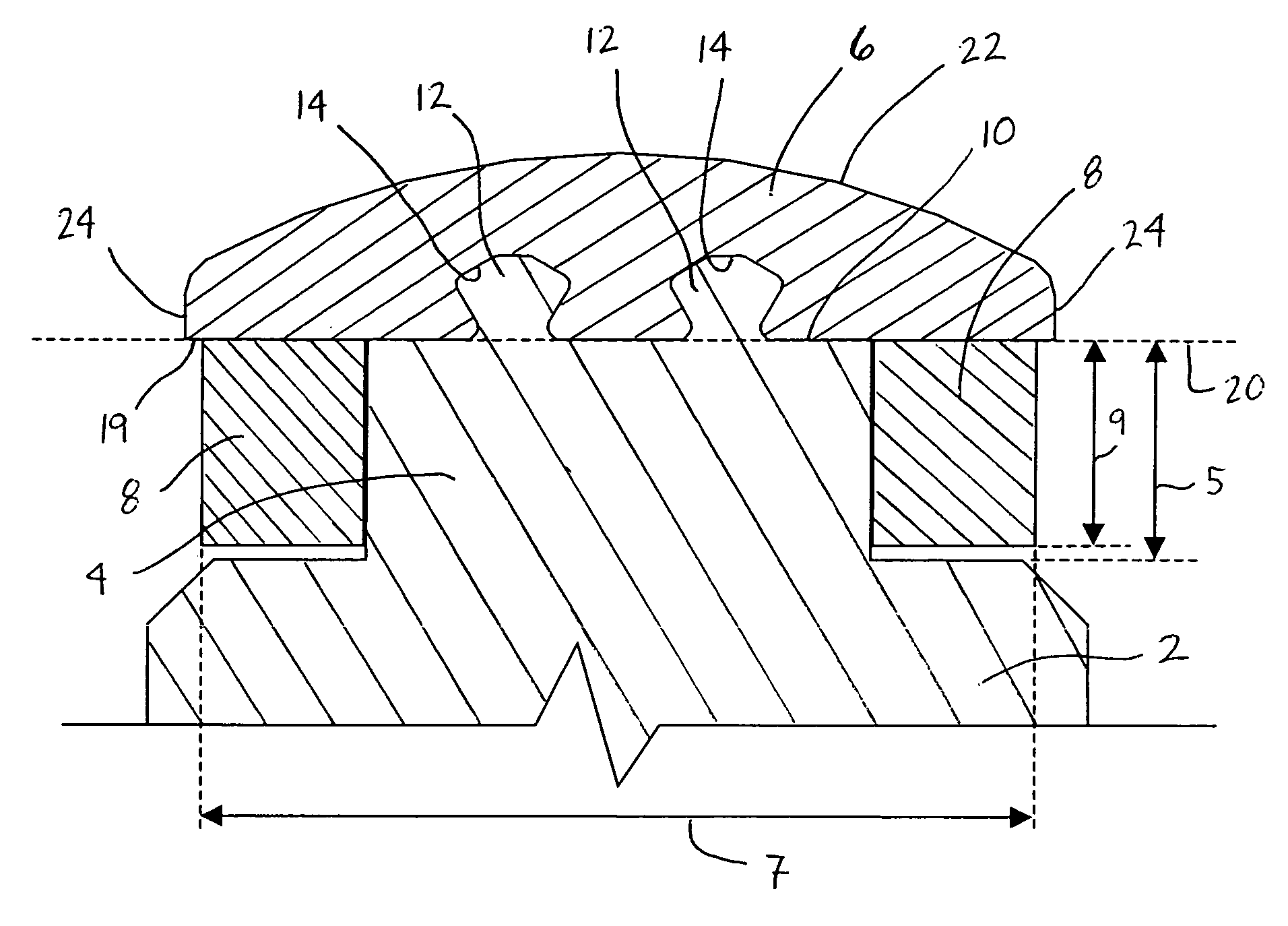
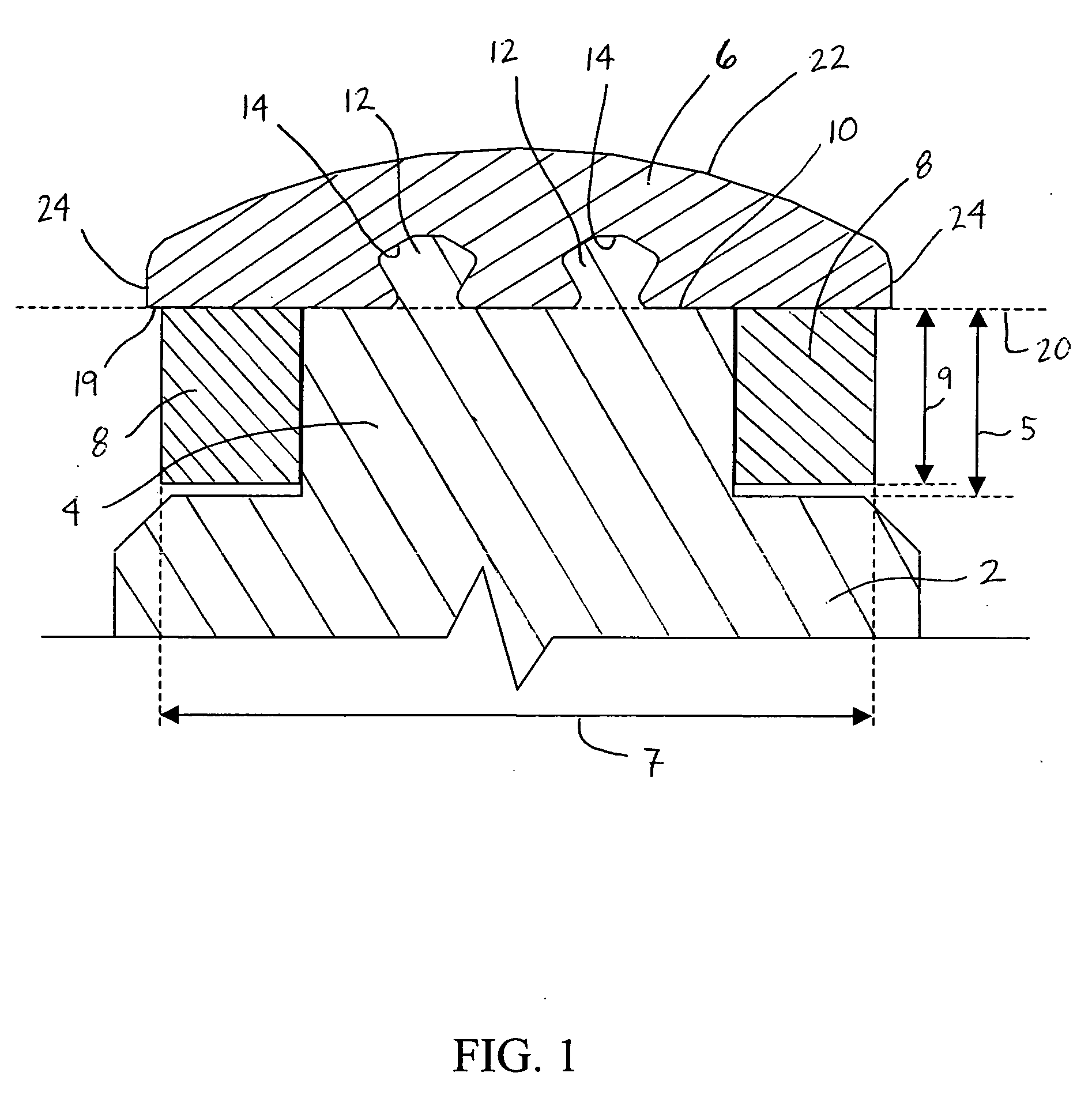
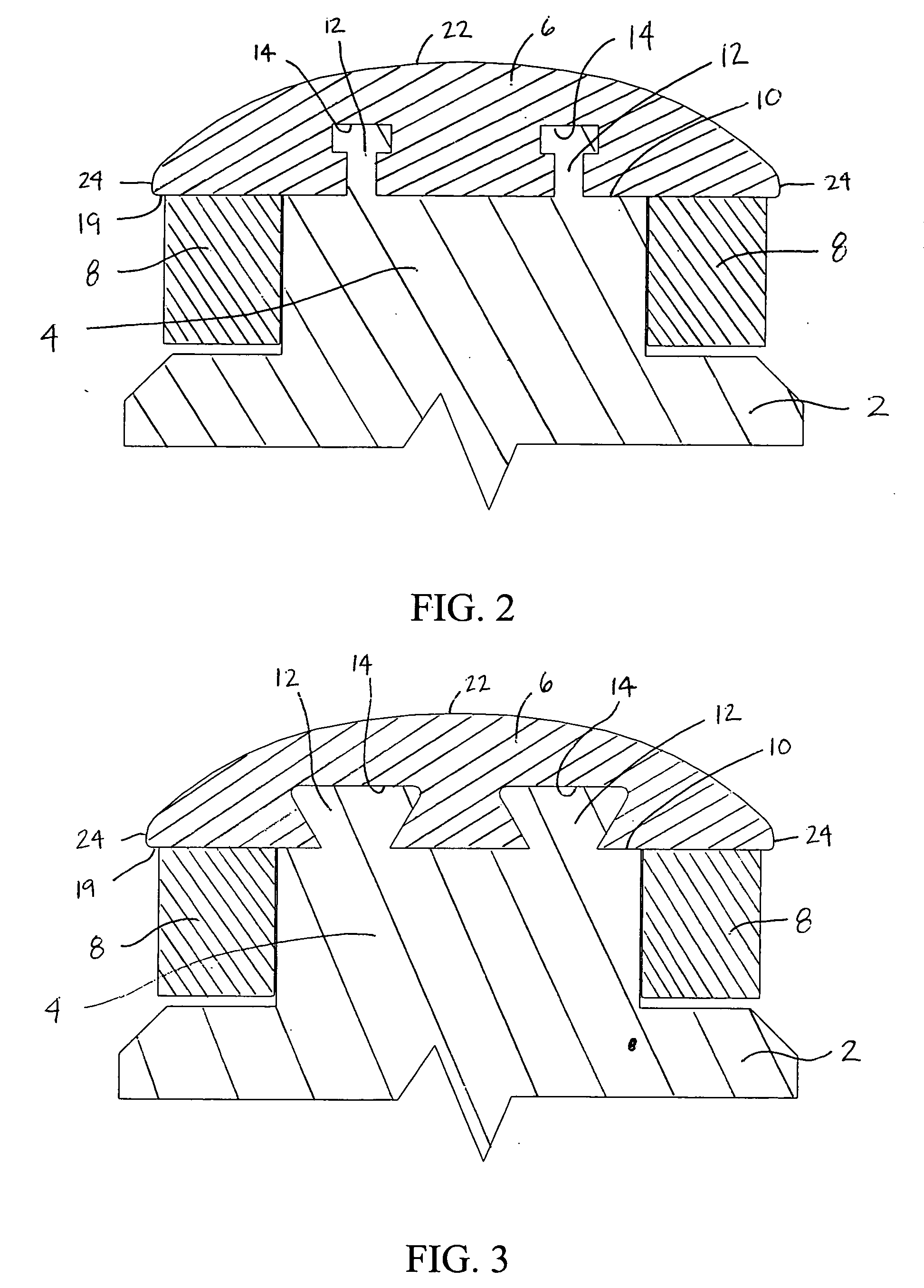
[0025] Thus, and by way of example, an apparatus “comprising” a rotor body; a non-laminated pole body extending from the rotor body, the non-laminated pole body having a top surface and a male connector projecting from the top surface; and a non-laminated pole tip having a female connector configured to connect to the male connector of the non-lam...


PUM


Abstract

Pole body and pole tip connections used with rotating machines. In one embodiment, a rotor body; a non-laminated pole body extending from the rotor body, the non-laminated pole body having a top surface and a male connector projecting from the top surface; and a non-laminated pole tip having a female connector configured to connect to the male connector of the non-laminated pole body. Other embodiments of the present apparatuses are included.

Description

BACKGROUND OF THE INVENTION [0001] 1. Field of the Invention [0002] The invention relates generally to the field of rotating machines, such as motors and generators. More particularly, it relates to pole body and pole tip connections used with such machines. [0003] 2. Description of Related Art [0004] For high horsepower and high-speed (1,500 RPM or more) synchronous motors and generators, solid poles (including pole body and pole tip) are typically used. Due to thermal limitations, copper sheets (known in the art as strap winding) are typically used for the rotor windings (also known in the art as rotor field windings or field windings) to improve thermal conductivity and to reduce temperature rise. [0005] For solid pole designs, pole tips and pole bodies have been made integral with each other and the resulting poles have been either integral with the rotor body or connected to the rotor body using one or more dovetail connections (the rotor body having the male connector and the ...

Claims


Application Information

Patent Timeline
Patent Type & Authority Applications(United States)
IPC IPC(8): H02K1/08
CPCH02K1/08
Inventor ZHONG, PING
Owner TECO WESTINGHOUSE MOTOR
Why Eureka
Try Eureka