Time-sequential colour projection

a colour projector and time-sequence technology, applied in the field of time-sequence colour projectors, can solve the problems of increasing the high cost of the system, and low optical efficiency of the projector, and achieves the effects of low cost, reduced visibility of flicker and colour artefacts, and high illumination efficiency

Inactive Publication Date: 2005-11-17
SHARP KK
View PDF4 Cites 78 Cited by
  • Summary
  • Abstract
  • Description
  • Claims
  • Application Information

AI Technical Summary

Benefits of technology

[0055] It is thus possible to provide a time-sequential colour projector which has all of the advantage of known projectors of this type. For example, the projected images have the full spatial resolution of the light valve or valves and no light is absorbed by colour filters so that the light-efficiency is relatively high. Also, the visibility of flicker and colour artefacts is reduced compared with known time-sequential colour designs because the whole image frame does not change colour at the same time. In addition, the use of electronic light sources provides high efficiency of illumination, relatively long light source lifetime, robustness, and reduced cost.

Problems solved by technology

A fast light valve (such as a micromirror device) is necessary and these are typically more expensive than relatively slow light valves such as transmissive liquid crystal panels.
This means that the optical efficiency of the projector is low.
The three-panel system has the disadvantage that three panels and colour separating and combining optics are required, increasing the cost of the system.
Also, the images from the three panels must be made to converge with high precision, thus complicating the manufacturing process.
A disadvantage is that the spatial resolution of the system is reduced by a factor of three.
Another disadvantage is that, in order to achieve a high throughput of light, the microlens arrays must have a low f-number.
This is possible in principle, but means that light valves must be specially manufactured for this purpose, thus increasing the cost and complexity.
Systems with angular colour separation, as described above, suffer from the problem that the resolution is reduced by a factor of three compared to the base panel.
The problem of reduced resolution for angular colour separation is thus removed but the problem of panel-barrier separation remains.
However, it has the disadvantage that because macroscopic lenses are used, aberrations may make it difficult to align the system.
Also, because a lens at least the size of the panel is required, the microlens array must be separated from the panel by at least two panel diameters: this increases the size of the system.
This type of LED projector has the disadvantage that at least two-thirds of the light is absorbed by the filters.
It is therefore inefficient in its use of light.
Its disadvantages are the presence of flicker and colour defects if the frame rate is not high enough and the fact that the panel must run at at least three times video speed, which makes it expensive.
However, the use of three panels adds to the cost and bulk of the projector.
This design has high light efficiency but has the disadvantage of requiring high-speed mechanical scanning apparatus, which is expensive and unreliable.

Method used


Image

  • Time-sequential colour projection
  • Time-sequential colour projection
  • Time-sequential colour projection

Examples


Embodiment Construction

[0073] Like reference numerals refer to like parts throughout the drawings.

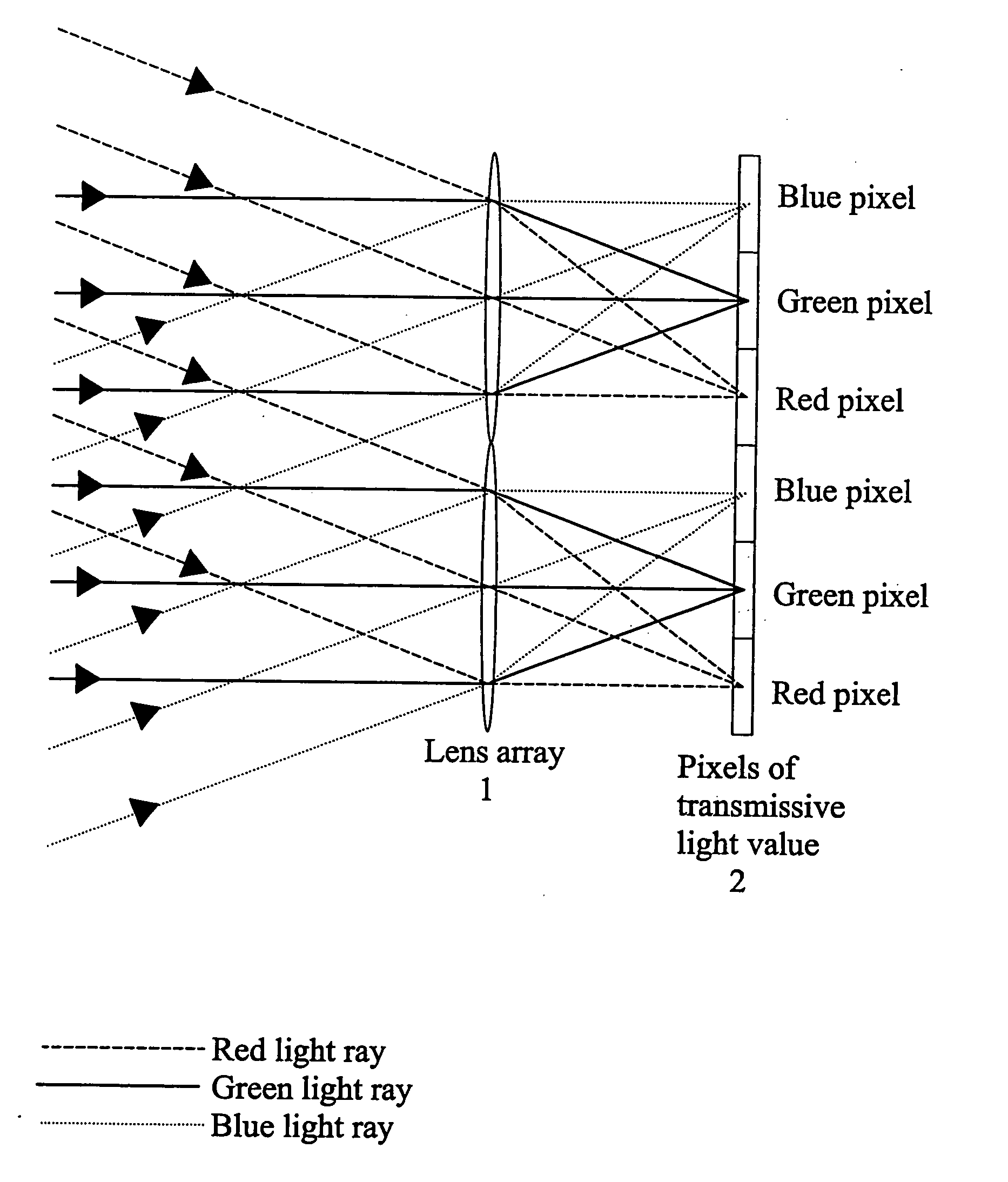
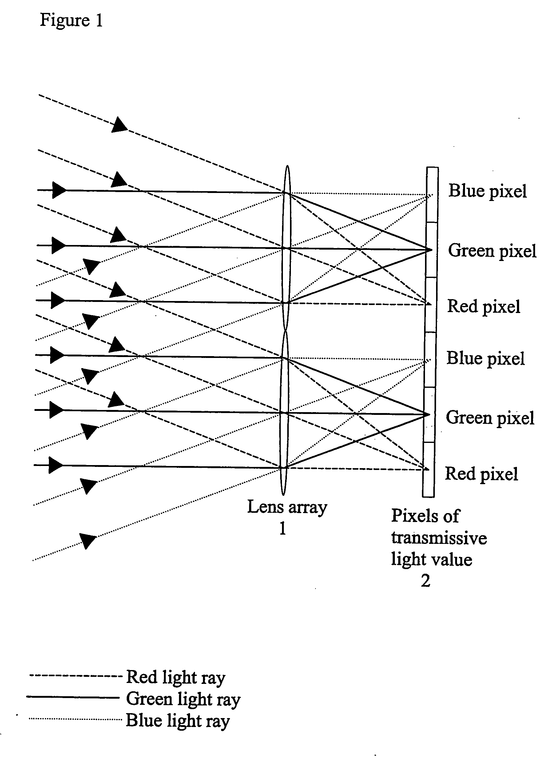
[0074] As described hereinbefore, FIG. 1 illustrates part of the light path in a known type of angular colour projector. The red light path is illustrated by the broken lines, the green light path by the solid lines and the blue light path by the dotted lines. Red, green and blue light rays are incident on a lens array 1 at different angles or in different angular ranges. The lens array 1 is disposed in front of the pixels of a transmissive light valve 2, such as a liquid crystal device. The pitch of the lens array 1 is substantially equal to three times the pitch of the light valve pixels 2 with each lens of the array 1 being aligned with three pixels or three rows of pixels of the light valve. Light incident on the lens array 1 is substantially collimated and the pixels of the light valve are disposed substantially in the focal plane of the lens array 1. Thus, the red, green and blue light rays are focused...


PUM


Abstract

A time-sequential colour projector comprises a pixellated light valve (2), such as a liquid crystal device, and a plurality of light sources (30, 31, 32). The light sources (30, 31, 32) direct light on different sets of pixels of the light valve (2) via an optical system (1), such as a lens array, which focuses the light on pixels of the light valve (2). At least two of the light sources (30, 31, 32) are multiple colour light sources and the multiple colour light sources emit different colour components during each set of frames making up a complete image frame.

Description

BACKGROUND OF THE INVENTION [0001] 1. Field of the Invention [0002] The present invention relates to a time-sequential colour projector. Applications of such projectors include video and data projectors used to project images from electronic data sources. Such projectors include front and rear projectors, projectors for cinema and home entertainment, projectors for head-up displays in vehicles, projectors for business and conference applications and miniature portable projectors. [0003] 2. Description of the Related Art [0004] Electronic projectors typically make use of one or more ‘light valves’, which are typically planar devices divided into pixels. The fraction of incident light which each pixel transmits or reflects can be controlled independently. A projector also contains an optical system for illuminating such a light valve, electronics for controlling the valve, and an optical system for projecting an image displayed by the light valve on a screen. [0005] Three types of lig...

Claims


Application Information

Patent Timeline
Patent Type & Authority Applications(United States)
IPC IPC(8): G03B21/14G02B5/30G02B27/10G02B27/14G03B21/00H04N9/31
CPCG02B27/1046G02B27/1053G02B27/149G02B27/145G02B27/123
Inventor EVANS, ALLANBOURHILL, GRANTKHAZOVA, MARINA V.
Owner SHARP KK
Why Eureka
Try Eureka