Method and device for creating 3-dimensional view image

a three-dimensional view and image technology, applied in the field of three-dimensional image data generation, can solve the problems of not being able to calculate the true z-value of the object, not being able to reproduce the correct parallax of the generated stereographic image, and being given an unnatural impression by the viewer

Inactive Publication Date: 2005-11-17
MERCURY SYSTEM CO LTD
View PDF1 Cites 81 Cited by
  • Summary
  • Abstract
  • Description
  • Claims
  • Application Information

AI Technical Summary

Problems solved by technology

This is because edges of distant objects tend to be fine due to dust in the air and the like, blurring the object.
As a result, it is not possible to reproduce a correct parallax with the generated stereographic image, and a viewer is thus given an unnatural impression.
Further, in a case where a shadow or a highlight hangs over a certain portion of an object, in other words in a case where a variation of saturation within the object is considerable, it is not possible to calculate a true Z-value of the object.
In this case, since it is not possible to determine an edge of objects precisely, the blurring process cannot contribute to improvement of plasticity of the 3D image.
As a result, a quality of a generated stereographic image is reduced to such an extent that it cannot be appreciated by a viewer.
Occurrence of this phenomenon is especially serious at a position where a number of objects overlap.
At such a position, distortion of the image can occur easily; thus it becomes significantly difficult to achieve natural perception of a stereographic image for a viewer.
As is described above, since it is not possible in the prior art to calculate a correct Z-value from an original image data to generate a stereographic image, generation of a realistic stereographic image is difficult.

Method used


Image

  • Method and device for creating 3-dimensional view image
  • Method and device for creating 3-dimensional view image
  • Method and device for creating 3-dimensional view image

Examples


first embodiment

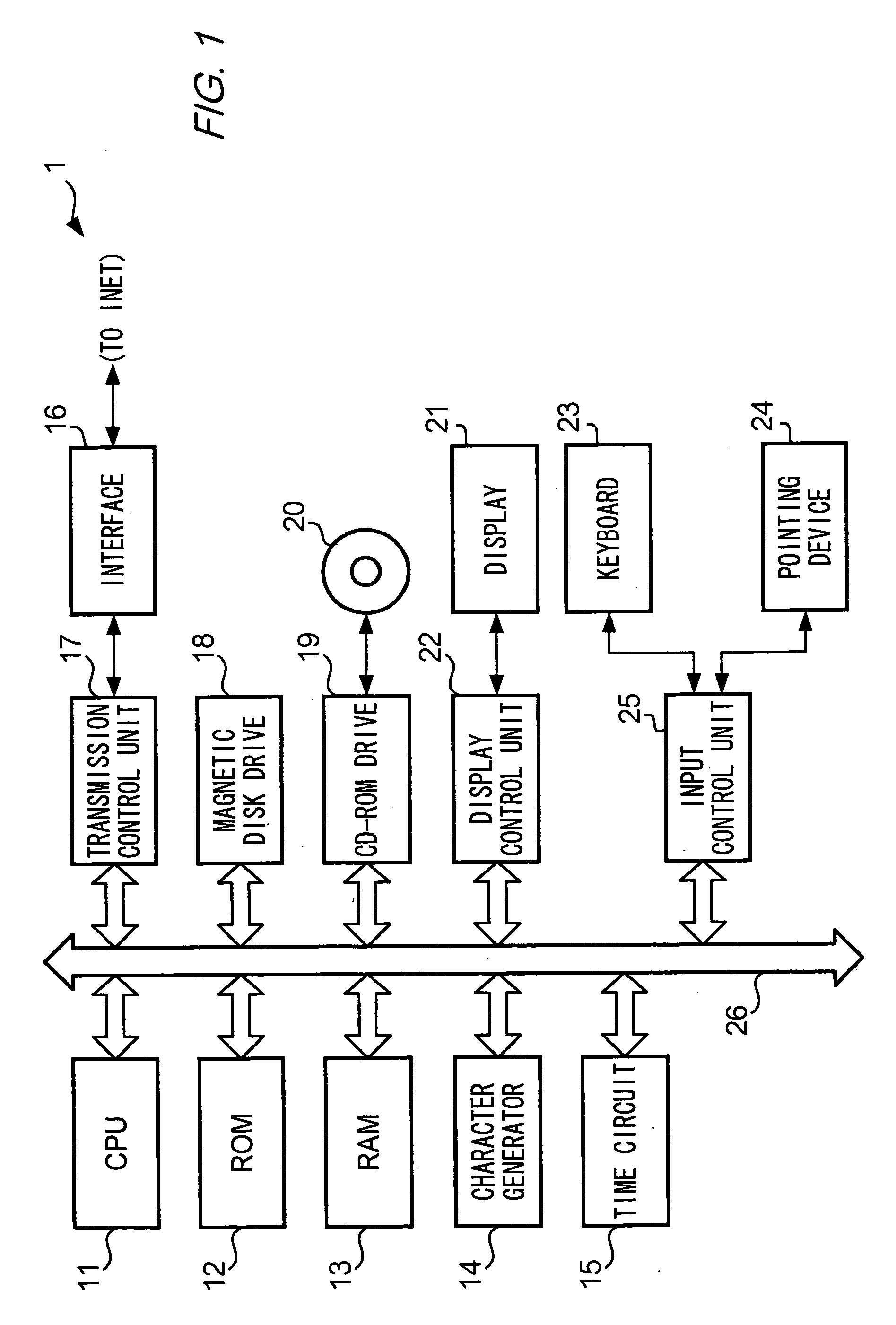
[0074]FIG. 1 shows a 3D image generating apparatus 1 of the first embodiment of the present invention. In FIG. 1, a CPU (central processing unit) 11 controls all units of 3D image generation apparatus 1 to perform processing including generation of stereographic image data. A ROM (read only memory) 12 is employed to store programs, one of which is executed when the apparatus is turned on, and related data. A RAM (random access memory) 13 is employed as a work area of CPU 11.

[0075] A Character generator 14 generates font data to be displayed on a display. A Time circuit 15 outputs a current time. An Interface 16 connects 3D image generation apparatus 1 to the Internet (not shown). A Transmission control unit 17 transmits and receives data to and from terminals connected to the Internet.

[0076] A Magnetic disk drive 18 stores programs for performing image processing executed by 3D image generation apparatus 1, including an OS program and data generated in the image processing steps. ...

second embodiment

[0213] The second embodiment of the present invention will now be described. Like numerals are assigned to like elements of the first embodiment. The second embodiment differs from the first embodiment in that a Mobile terminal 1A is used instead of 3D image generation apparatus 1. FIG. 43 shows a functional configuration of Mobile terminal 1A and FIG. 44 shows an external view of Mobile terminal 1A. As shown in FIG. 44, Mobile terminal 1A is, for example, a mobile phone. The following description mainly describes differences between the first and the second embodiments.

[0214]FIG. 43 shows a radio communication unit 27, which includes an antenna AT, for connecting Mobile terminal to a mobile communications network to transmit and receive data such as moving images data. The network includes a communications unit 28, which includes a speaker unit and a microphone unit, for carrying out a voice communications. A Display 21a has a function of displaying 2D mode images and 3D images al...

third embodiment

[0230]FIG. 49 shows a functional configuration of a 3D generating apparatus 1B of the third embodiment. 3D generating apparatus 1B differs from 3D generating apparatus 1 of the first embodiment in having a Display control unit 22b, the first data buffer 31, and the second data buffer 32 instead of Display control unit 22, and having a Display 21b instead of Display 21. In this embodiment, a scheme for exciting stereopsis in a user wearing Glasses 34 in which liquid crystal shutters are disposed is used.

[0231] Similarly to the second embodiment, in 3D image generating apparatus 1B stereogram mode and normal mode can be selected. In 3D mode, Display control unit 22b stores image data for the left and the right eyes in First data buffer 31 and Second data buffer 32, respectively. Display control unit 22b controls a Switch 33 to select First data buffer and Second data buffer alternately. Specifically, a screen is refreshed at a predetermined time interval on Display 21b, and Display c...


PUM


Abstract

In a 3D image generating apparatus 1 depth values (Z-value) of pixels are calculated on the basis of grayscale values of 2D image data. Next, a reverse determination, smoothing, distribution adjustment, local adjustment, and the like are performed on the Z-values. Next, parallaxes of pixels are determined on the basis of the Z-values of the pixels finally obtained, and the pixels are displaced acceding to the parallaxes, so as to generate data of a stereographic image.

Description

TECHNICAL FIELD [0001] The present invention relates to a method and apparatus for generating three-dimensional image data by means of two-dimensional image data. BACKGROUND ART [0002] Humans are able to visually perceive three-dimensional objects in three-dimensional space. This ability is known as stereopsis. Stereopsis occurs when a human brain recognizes an object in three-dimensions on the basis of two images, received by the right and the left eyes, respectively. In other words, it is necessary for each of the right and the left eyes to receive an image for stereopsis to occur. [0003] A technique called stereography has been developed, in which image processing is performed on a two-dimensional image so that a viewer can perceive the processed two-dimensional planar image as a three-dimensional image. Stereography involves an image processing technique of revising image data of a single two-dimensional planar image to generate image data for each of the right and left eyes. Sp...

Claims


Application Information

Patent Timeline
Patent Type & Authority Applications(United States)
IPC IPC(8): G06K9/00H04N15/00
CPCH04N13/026H04N2213/003H04N13/0434H04N13/0275H04N13/261H04N13/275H04N13/337G06T15/10H04N13/00
Inventor ERA, KAZUNARI
Owner MERCURY SYSTEM CO LTD
Why Eureka
Try Eureka