
Grain bin sweep and method of assembly

a technology of grain bins and sweeps, which is applied in the field of bin sweeps, can solve the problems of damage to the sweep arm including the support frame, the auger and the backshield, and the large downward pressure created by the flow of grain, and achieves the effect of increasing the overall length of the frame and being easy to maneuver

Inactive Publication Date: 2005-11-17
SUDENGA INDS
View PDF19 Cites 29 Cited by
  • Summary
  • Abstract
  • Description
  • Claims
  • Application Information

AI Technical Summary

Benefits of technology

[0009] The present invention is directed to the structure of a support frame for a grain bin sweep that can be used inside a grain bin. The support frame is comprised of several longitudinally extending panels that when assembled create an open interconnected design. The panels are attached together on their longitudinal sides to create an open structure which allows for the free flow of grain through the frame. In one embodiment, additional panel sections can be added to the end of the frame in order to increase the overall length of the frame to a specified size.
[0010] In one embodiment, the support frame is triangular in shape (when viewed laterally) and is comprised of three panels attached together along the longitudinal sides of each respective panel. The panel assembly design of the structure of the frame makes it easy to bring sections of the frame into a grain bin and to assemble them in the grain bins as they are easy to place into position. The open framework of the panels also make the panels lighter and easier to maneuver.

Problems solved by technology

Therefore, the grain sweep usually has a lot of weight (from the grain) pressing down upon it.
The downward pressure created from the flow of grain is so great that at times, the sweep arm including the support frame, auger and backshield become damaged (i.e., crushed or warped).
Another problem with most grain sweeps is that they are difficult to transport and difficult to assemble within a grain bin because the frame is constructed as one structure.
This makes if difficult to bring that structure into an existing grain bin, and to position, assemble and install the frame because of the length of the support frame.
In addition, the repair of the grain sweep may require the removal of the frame from the bin, which is inconvenient because of its size.
This means that the grain sweep cannot be easily removed and taken to another silo, especially one that is of a different size.

Method used


Image

  • Grain bin sweep and method of assembly
  • Grain bin sweep and method of assembly
  • Grain bin sweep and method of assembly

Examples


Embodiment Construction

[0018] The present invention allows for the free flow of grain through the support structure while still assisting in providing additional strength to the sweep arm. The present invention also allows for ease of assembly of a support frame within a grain storage facility. The present invention is further explained with reference to the drawing figures, wherein like structures are referred to by like numbers throughout the several views.

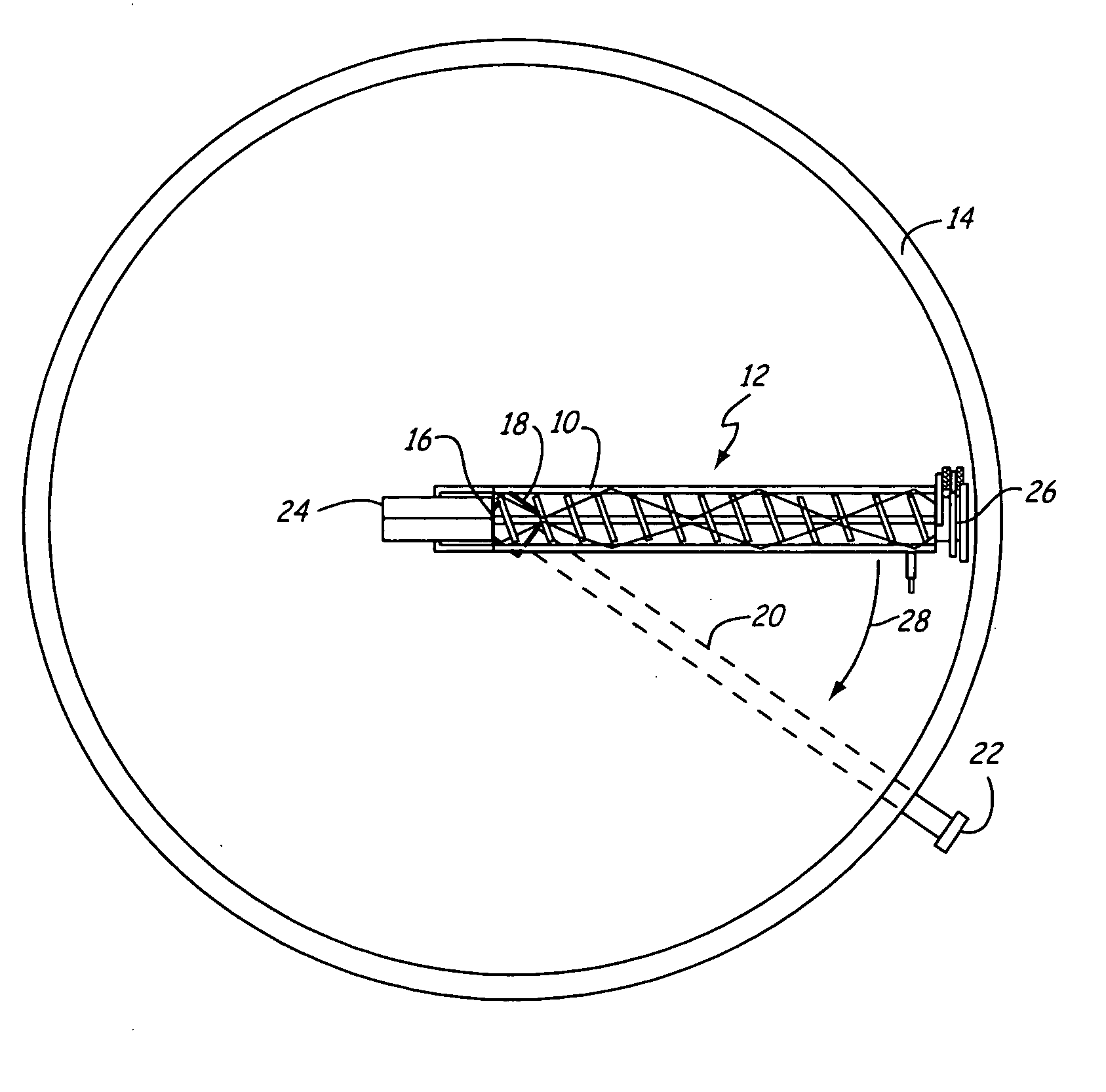
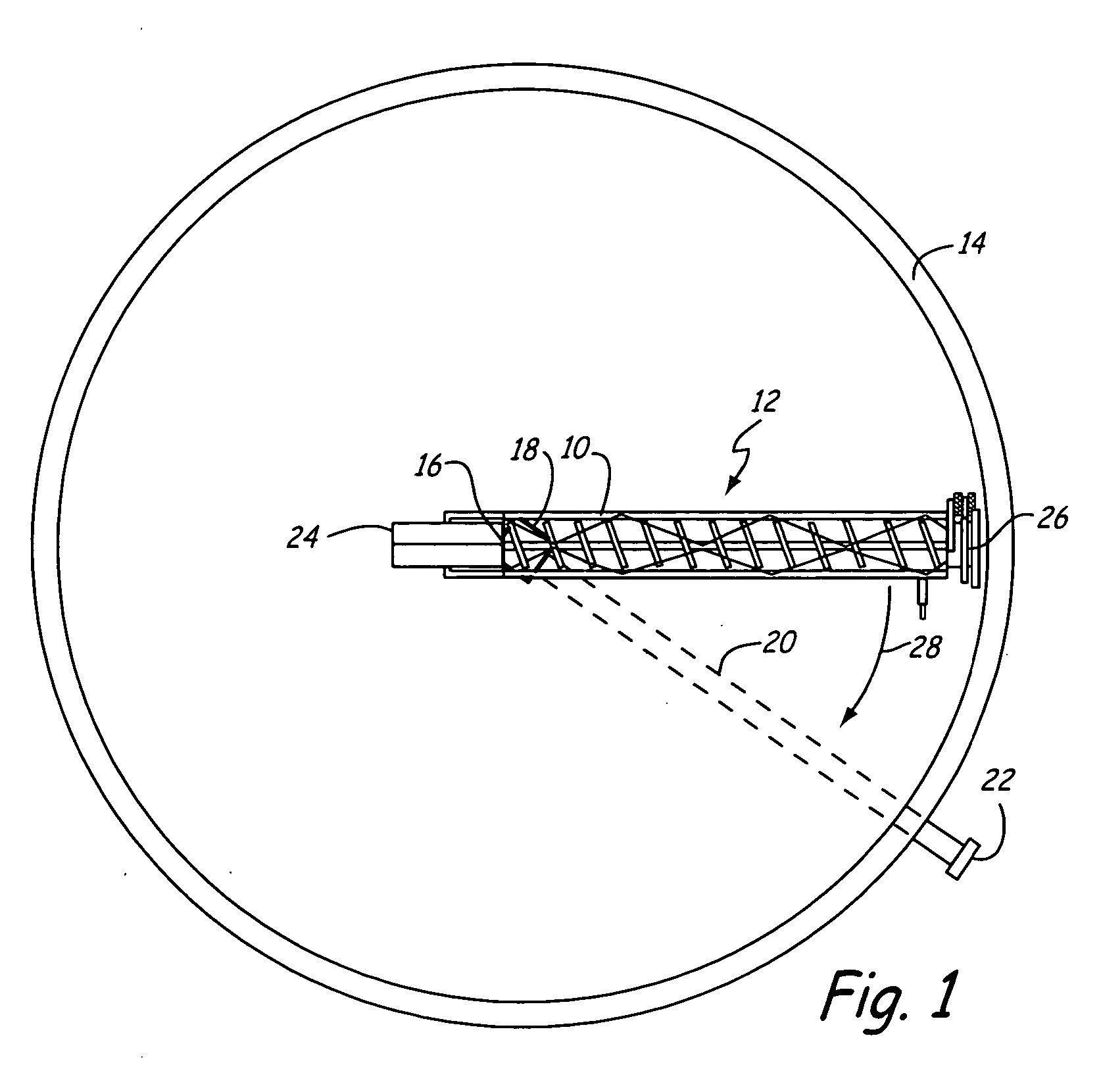
[0019]FIG. 1 shows a top view of support frame 10 as it would appear in use on bin sweep 12 in grain bin 14. Grain bin 14 is a storage facility, typically cylindrical, well known within the art. Bin sweep 12 rotationally moves around pivot axis 16 within grain bin 14. Bin sweep 12 conveys grain in the grain bin 14 from the outer circumference of grain bin 14 to a floor opening 18. Typically, floor opening 18 is centrally located within the bin with pivot axis 16 centrally located within the area of floor opening 18. Upon reaching floor opening 18, th...


PUM


Abstract

A support frame for a grain bin sweep has an open interconnected framework which allows grain to flow through the frame. The frame is comprised of panels which are assembled together to form an open structure frame. The structure of the frame allows for easy mobility and assembly while still able to withstand the tremendous pressure exerted by large amounts of grain disposed on top of the grain bin sweep in a grain bin.

Description

CROSS-REFERENCE TO RELATED APPLICATION(S) [0001] None BACKGROUND OF THE INVENTION [0002] This invention relates to bin sweeps for moving and clearing of grain and other materials from silos, grain bins and similar storage units. Specifically, this invention relates to an open support frame that helps to support the auger of a bin sweep. [0003] A grain bin sweep is generally found at the bottom of a grain bin containing a flat bottom floor. Typically, the grain bin has a circular horizontal cross-section. Diameters of grain bins vary from several feet to over one hundred feet. A grain sweep must cover, at a minimum, the radius of the bin so that it is able to sweep the entire area of the bin as it rotates about an axis in the center of the grain bin. [0004] Commonly, an interior grain storage cavity of a grain bin or silo is filled with grain while the grain sweep is positioned at the bottom of the silo. Therefore, the grain sweep usually has a lot of weight (from the grain) pressing...

Claims


Application Information

Patent Timeline
Patent Type & Authority Applications(United States)
IPC IPC(8): B65G1/00B65G65/46
CPCB65G65/466
Inventor BERREAU, ARVID JAMESHASS, LYNDON JOHN
Owner SUDENGA INDS
Features
  • Generate Ideas
  • Intellectual Property
  • Life Sciences
  • Materials
  • Tech Scout
  • Unparalleled Data Quality
  • Higher Quality Content
  • 60% Fewer Hallucinations
Learn More