Fan revolution speed control method

a technology of speed control and fan, which is applied in the direction of rotary clutches, positive displacement liquid engines, fluid couplings, etc., can solve the problems of pressure hunting of the motor outlet pressure, possible damage to the pump motor system, so as to prevent the generation of peak pressure, reduce the burden, and prevent the effect of pressure hunting

Inactive Publication Date: 2005-11-17
CATEPILLAR SARL
View PDF4 Cites 21 Cited by
  • Summary
  • Abstract
  • Description
  • Claims
  • Application Information

AI Technical Summary

Benefits of technology

[0008] A fan revolution speed control method according to the present invention is a method of controlling the fan revolution speed of a cooling fan that is adapted to be rotated by a fan motor so as to cool a cooling target fluid, wherein the control of the fan revolution speed is executed by controlling the pump-motor system that serves to drive the aforementioned fan motor by means of hydraulic fluid supplied from an engine-driven fan pump, the control of the pump-motor system comprising steps of detecting a temperature of a cooling target fluid, determining a target fan revolution speed of the cooling fan based on the detected temperature of the cooling target fluid, and controlling the pump-motor system so that the fan revolution speed starts from a minimum fan revolution speed at the start-up of the engine and gradually increases to the target fan revolution speed. By controlling the pump-motor system so that the fan revolution speed starts from a minimum fan revolution speed at the start-up of the engine and gradually increases to the target fan revolution speed, in other words preventing a control signal corresponding to the target fan revolution speed that has been determined based on detected temperatures of the cooling target fluids from being step input into the pump-motor system at the start-up of the engine, the method according to the invention is capable of reducing burden imposed on the fan pump and the fan motor and preventing generation of peak pressure between the fan pump and the fan motor. Furthermore, as the difference between the pump discharge pressure of the fan pump, i.e. the motor inlet pressure of the fan motor, and the motor outlet pressure of the fan motor, is limited so as to prevent pressure hunting, damage to the fan motor is prevented. The aforementioned feature of the method is also effective in preventing a hunting of the fan revolution speed.
[0009] A fan revolution speed control method according to another feature of the invention is similar to the fan revolution speed control method described above and further characterized in that the minimum fan revolution speed is maintained for a given period of time at the start-up of the engine. By maintaining the minimum fan revolution speed for a given period of time at the start-up of the engine, the control method having this feature prevents fluctuation in burden imposed on the engine, thereby stabilizing the engine speed rapidly when the engine is started up.

Problems solved by technology

As the conventional method described above calls for step input of a control signal that corresponds to a target fan revolution speed or a maximum revolution speed at the start-up of an engine, a great load is applied to a pump-motor system, which comprises a system from a fan pump to a fan motor, and causes a peak pressure or pressure hunting, resulting in the possibility of damage to the pump-motor system.
As is evident from measurement data regarding pressures of the fan pump and the fan motor shown in the upper graph in FIG. 7, a peak pressure may be generated in the pump discharge pressure of the fan pump (or the motor inlet pressure), or a great difference may arise between the motor inlet pressure and the motor outlet pressure of the fan motor and cause pressure hunting of the motor outlet pressure.
Such a peak pressure or pressure hunting may cause damage to the pump-motor system, which comprises a system from the fan pump through a piping to the fan motor.

Method used


Image

  • Fan revolution speed control method
  • Fan revolution speed control method
  • Fan revolution speed control method

Examples


Embodiment Construction

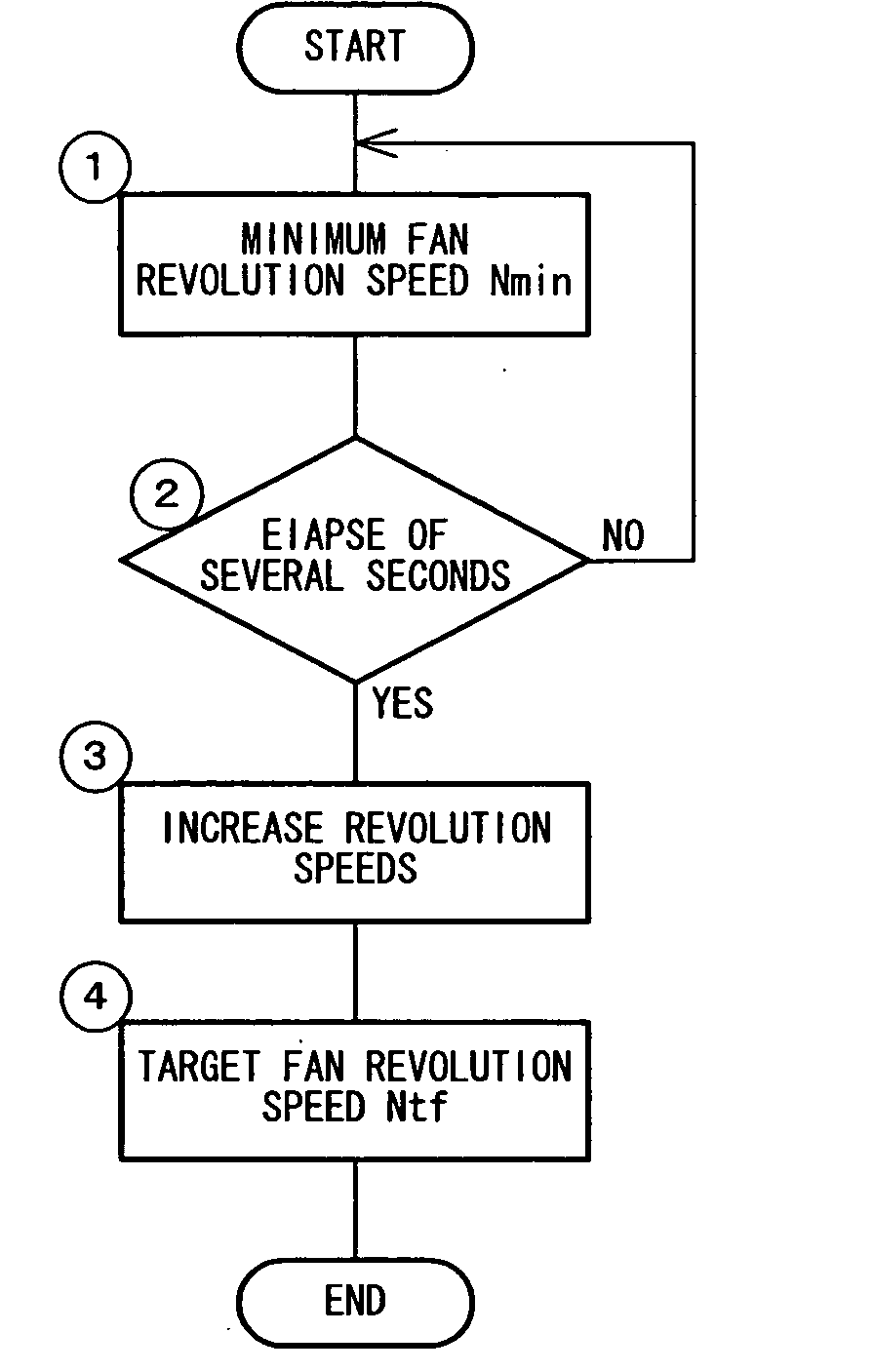
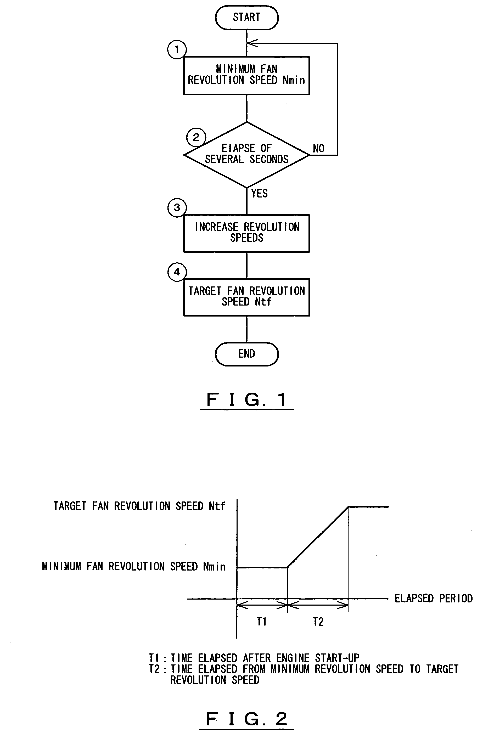
[0017] Next, the present invention is explained hereunder, referring to an embodiment thereof shown in FIGS. 1 through 6.

[0018]FIG. 4 shows an outline of a fan revolution speed control device. An engine 11, which is mounted on the motor vehicle of a construction machine, such as a hydraulic excavator, is provided with a main pump 12 for excavation or other work and a fan pump 13 and has a function of driving these pumps 12 and 13 together. The main pump 12 serves to feed hydraulic oil under pressure. The hydraulic excavator comprises an undercarriage and an upper structure. The undercarriage is provided with a traveling system, such as crawler belts. The upper structure is provided with a working unit system and rotatably mounted on the undercarriage, with a turning system disposed between the upper structure and the undercarriage. The working unit system comprises a boom, an arm, a bucket, and hydraulic cylinders for operating these components.

[0019] The main pump 12 serves to fe...


PUM


Abstract

The invention is a fan revolution control method for controlling a pump-motor system, by controlling the fan revolution speed of a cooling fan adapted to be rotated by a fan motor to cool cooling target fluids. The pump-motor system drives the fan motor by a hydraulic fluid fed from a fan pump driven by an engine. The pump-motor system is controlled so the fan revolution speed starts from the minimum fan revolution speed when the engine is started up; the minimum fan revolution speed is maintained for at least several seconds; after the elapse of several seconds, the fan revolution speed is gradually increased from the minimum fan revolution speed. The fan revolution speed reaches a target fan revolution speed over a period of at least several seconds. The method prevents generation of peak pressure or pressure hunting.

Description

TECHNICAL FIELD [0001] The present invention relates to a fan revolution speed control method for controlling a fan revolution speed of a cooling fan that is adapted to cool cooling target fluids. In the explanation hereunder, a number of revolutions per unit period of time is referred to as “revolution speed”. BACKGROUND OF THE INVENTION [0002] There are various conventional fan revolution control methods for controlling the fan revolution speed of a cooling fan adapted to be rotated by a fan motor, wherein the control of the fan revolution speed is executed by controlling the pump-motor system that serves to drive the aforementioned fan motor by means of hydraulic oil supplied from an engine-driven fan pump. Some of such control methods call for detecting a temperature of a fluid to be cooled (hereinafter referred to as cooling target fluid) by means of a temperature sensor and, based on the detected temperature of the cooling target fluid, determining a target fan revolution spee...

Claims


Application Information

Patent Timeline
Patent Type & Authority Applications(United States)
IPC IPC(8): F04D27/00F01P7/04F04B49/06F04D27/02
CPCF04D27/004F01P7/044Y02B30/70F01P5/04F01P7/04F04B49/06F04D27/00
Inventor FURUTA, HIDETOTOYOURA, NOBUMI
Owner CATEPILLAR SARL
Why Eureka
Try Eureka