
Conductive material and manufacturing method thereof

a technology of conductive materials and manufacturing methods, applied in the direction of dielectric characteristics, conductive layers on insulating supports, non-printed masks, etc., can solve the problems of inability to obtain sufficient durability inability to obtain sufficient durability, and inability to bend by 180 degrees. , to achieve the effect of superior bending resistance, superior bending property and low cos

Inactive Publication Date: 2005-11-17
NISCA KK +1
View PDF1 Cites 23 Cited by
  • Summary
  • Abstract
  • Description
  • Claims
  • Application Information

AI Technical Summary

Benefits of technology

The technical effect of this patent is to create a flexible conductor that can be easily bent without breaking or losing its electrical properties. This is achieved through a process where a layer of metal is integrated into a substrate, making use of existing materials like copper or aluminum. Additionally, the invention provides a cost-effective solution for producing these flexible conductors while maintaining their high quality.

Problems solved by technology

This patent discusses the development of techniques for creating RFID tags with flexible antennas that can bend without breaking or losing effectiveness. Current methods involve adding a thin layer of metal onto a surface, but these materials often fail after only one bending cycle. Conductive polymers and shape-memory alloys offer potential solutions, but they too struggle with maintaining their strength during repetitive bending. Additionally, shape-memory alloys require expensive components. Therefore, the technical problem addressed in this patent is how to make RFID tags with durable, flexible antennas that can withstand multiple bending cycles while remaining cost-effective.

Method used

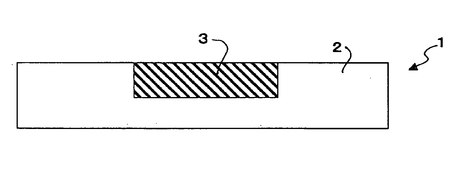
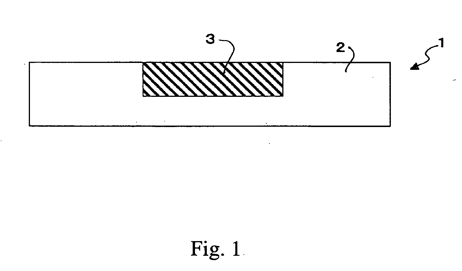
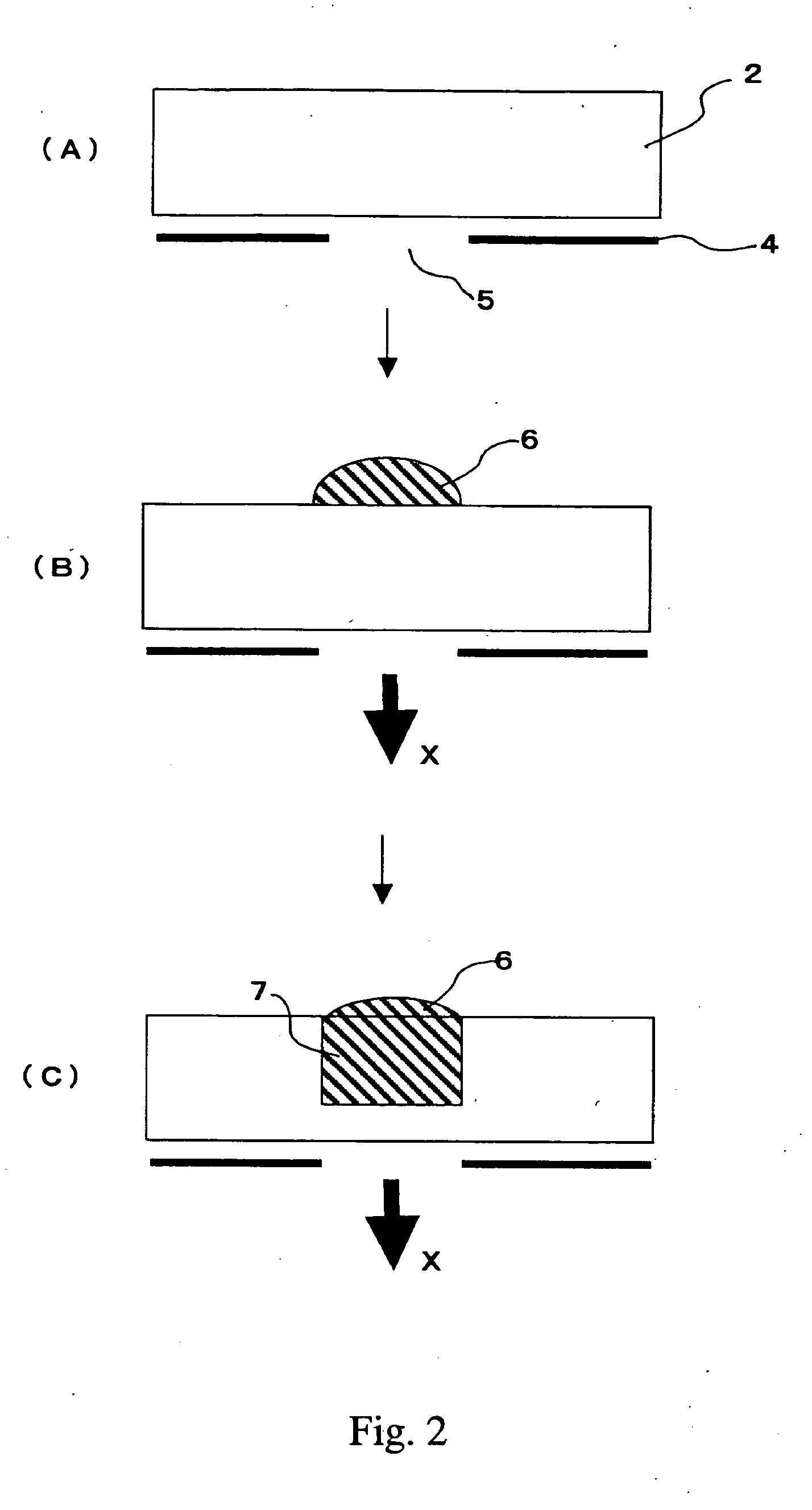

Image

  • Conductive material and manufacturing method thereof
  • Conductive material and manufacturing method thereof
  • Conductive material and manufacturing method thereof

Examples


example 1

[0085]

[0086] Carbon black, a conductor in a fine powder state, was mixed in water together with a dispersant. The mixture was stirred and dispersed sufficiently to prepare a conductor dispersion A having a solid component of 20.5% and a conductor dispersion D having a solid component of 35.2%. To these was added and mixed carbon nanofibers, another conductor in a fine powder state (trade name: VGCF, made by Showa Denko K.K.), the amount of which is listed below. The mixture was stirred and dispersed sufficiently to prepare conductor dispersions B, C and E to G listed in Table 1. At room temperature, each of the dispersions was measured in the viscosity (Pa·s) thereof at shear rates of 2.0 ( / s) and 50.0 ( / s) by using a rheometer (RS-100, made by HAAKE Co., Ltd., German company). The results thereof are also shown in Table 1. In Table 1, “CNF” represents “carbon nanofibers”.

TABLE 1Solid inViscosityViscosityconductorAmount of(Pa · s) at(Pa · s) atdispersionCNF mixedTotal solidshear r...


PUM

PropertyMeasurementUnit
Fractionaaaaaaaaaa
Fractionaaaaaaaaaa
Fractionaaaaaaaaaa

Abstract

The present invention provides a conductive material having superior bending property and superior bending resistant property and a method for manufacturing the same. This object is achieved by a conductive material comprising a substrate and a conductive portion formed within the substrate, wherein a change ratio in the electric resistance values before and after a bending resistant property test, in which the conductive portion is bent by 180 degrees and a load of 1 kg/cm2 is imposed on the bent portion for one hour, is set within a range of ±10%.

Description


Claims


Application Information

Patent Timeline
Owner NISCA KK
Learn More