Method for reducing stent weld profiles and a stent having reduced weld

a technology of stent and weld profile, which is applied in the field of stents, can solve the problems of polishing, deployment concerns, and the above-discussed deployment concerns, and achieve the effect of reducing the profile of welds and facilitating the capture or grabbing of the stent end

Inactive Publication Date: 2005-11-17
BOSTON SCI SCIMED INC
View PDF17 Cites 158 Cited by
  • Summary
  • Abstract
  • Description
  • Claims
  • Application Information

AI Technical Summary

Benefits of technology

[0020] The stent may further include a polymeric ring disposed over the exterior surface at the second open end. Additionally, the stent may further include a suture secured to one of the open ends. Such suture or sutures are useful for positioning, repositioning, and / or removing the stent. The suture can be a metallic, polymeric or textile suture loop threaded through the stent loops at one or both extremities of the stent. The suture loop may include a protruding part to help facilitate the capture or grabbing of the stent end.
[0021] In another aspect of the present invention, an implantable stent includes a plurality of wires arranged to form a hollow tubular structure having a tubular wall to define an interior surface and an exterior surface and having opposed open first and second ends, where the wires terminate at the second open end ends and adjacently abutting wires are welded at the second open end with a welding material to provide welds, and further where at least a portion of the welded material has been removed by chemical or electrochemical polishing to reduce the profile of the welds.

Problems solved by technology

The high profile regions are undesirable, often leading to deployment concerns, including higher deployment forces.
Such polishing, however, has not been attempted to alleviate the above-discussed deployment concerns.

Method used


Image

  • Method for reducing stent weld profiles and a stent having reduced weld
  • Method for reducing stent weld profiles and a stent having reduced weld
  • Method for reducing stent weld profiles and a stent having reduced weld

Examples


Embodiment Construction

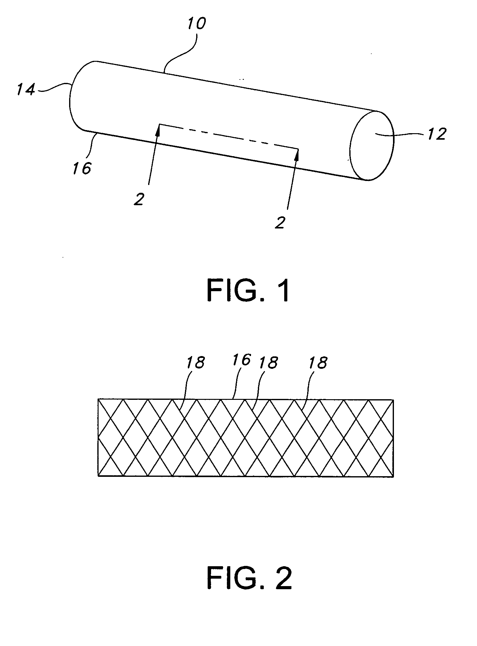
[0040] The present invention overcomes the deficiencies of the prior art by providing, among other things, low profile stent welds that reduce stent deployment forces. FIG. 1 depicts stent 10 of the present invention. Stent 10 is a hollow tubular structure having opposed open ends 12, 14 and having a tubular wall 16 therebetween. A portion of the tubular wall 16 is depicted in FIG. 2 as having a plurality of elongate wires 18 formed into the tubular wall 16. The elongate wires 18 traverse the length of the stent 10 in a direction traverse to the longitudinal length of the stent 10. The elongate wires 18 may be formed into the tubular wall 16 by braiding the wires 18, winding the wires 18, knitting the wires 18, and combinations. Preferably, the wires 18 are braided to form the tubular wall 16.

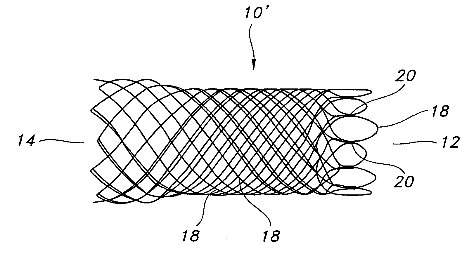
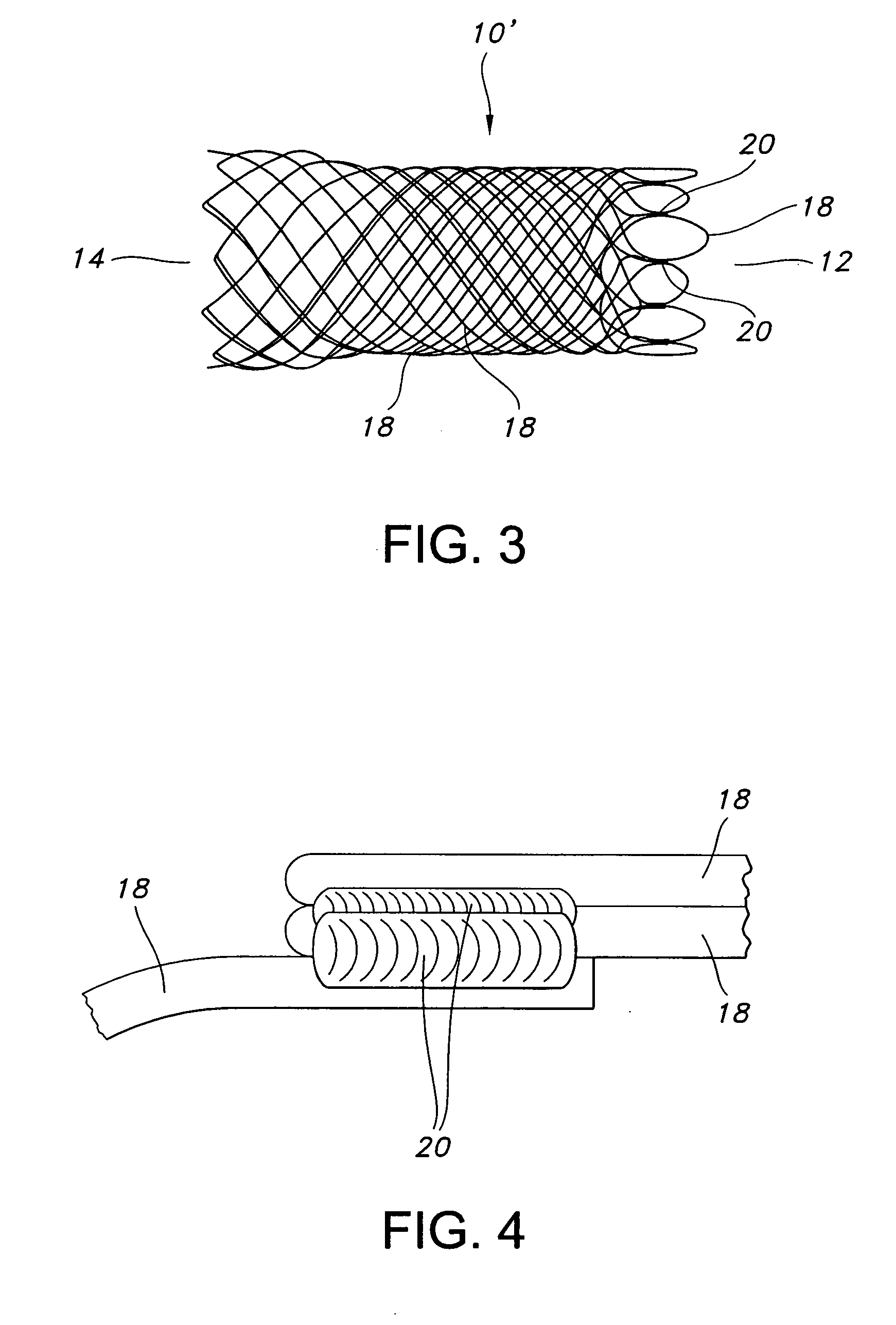
[0041] A welded stent 10′ according to the present invention is depicted in FIG. 3. The elongate wires 18 terminating at open end 12 are mated and adjacently mated wires are secured to one and...


PUM

PropertyMeasurementUnit
diameteraaaaaaaaaa
velocityaaaaaaaaaa
chemical oraaaaaaaaaa

Abstract

A method for making an implantable stent includes the steps of (i) providing a plurality of elongate stent wires; (ii) forming said wires into a hollow tubular structure having opposed first and second open ends; (iii) terminating said wires at the second end; (iv) aligning the wires at the second end into a plurality of mated adjacent wires to define a plurality of abutting regions; (v) welding the mated adjacent wires to one and the other at the abutting regions to define a plurality of welds; and optionally (vi) chemically or electro-chemically removing a portion of the welds. The method may further include the steps of (a) extending at least one of the mated stent wires to provide an extended stent wire; (b) looping the extended stent wire so the extended end abuts a proximal pair of stent wires; and (c) welding the extended and looped wire to the proximal pair of wires. The step of looping may include the forming of the wire into a equilaterally arched loop having an apex, but not having other sharp bends.

Description

FIELD OF THE INVENTION [0001] The present invention relates to stents having welded portions and atraumatic looped ends. The present invention also relates to such stents having their welded portions electro-chemically polished to reduce their profile and / or having a suture loop threaded at one or both extremities and / or being manufactured with a wire having a radiopaque core, and / or being fully or partially covered with a polymer such as silicone. BACKGROUND OF THE INVENTION [0002] Stents made from interconnecting, often braiding, elongate wires may be made less traumatic, i.e., atraumatic, by closing the loose wire ends at the ends of the stents. The loose wire ends have typically been closed by mechanical means, such as by clamps, for example clamped microtubes, or by welding. Such mechanical means, however, provide regions of high profile as compared to the other regions of the stents, see e.g., U.S. Pat. No. 6,083,257. The high profile regions are undesirable, often leading to ...

Claims


Application Information

Patent Timeline
Patent Type & Authority Applications(United States)
IPC IPC(8): A61F2/90B23K9/00B23K11/00B23K15/00B23K26/12B23K26/20B23K37/08C23F3/04C25F3/16
CPCA61F2/90A61F2230/0013B23K11/008B23K15/008B23K26/12B23K26/123B23K26/203B23K37/08B23K2201/06B23K2201/22B23K2201/32C23F3/04C25F3/16D04C1/06D04C3/48D10B2509/06D10B2403/0112A61F2220/005A61F2220/0058A61F2230/001B23K9/0026B23H9/02B23K26/211B23K2101/06B23K2101/22B23K2101/32
Inventor CLERC, CLAUDE O.NORTON, PAUL K.ZUPKOFSKA, MICHAELLEANNA, GARY J.ROBERTS, GEORGE TOM
Owner BOSTON SCI SCIMED INC
Why Eureka
Try Eureka