
Method of evaluation of space systems for safety assurance and residual risk to flightcrew

a technology of safety assurance and flight crew, applied in the field of process used to evaluate manned space systems for safety assurance and residual risk to flight crew, to achieve the effect of improving the survival rate of astronaut operating crew

Inactive Publication Date: 2005-11-17
NORTHROP GRUMAN CORP
View PDF13 Cites 24 Cited by
  • Summary
  • Abstract
  • Description
  • Claims
  • Application Information

AI Technical Summary

Benefits of technology

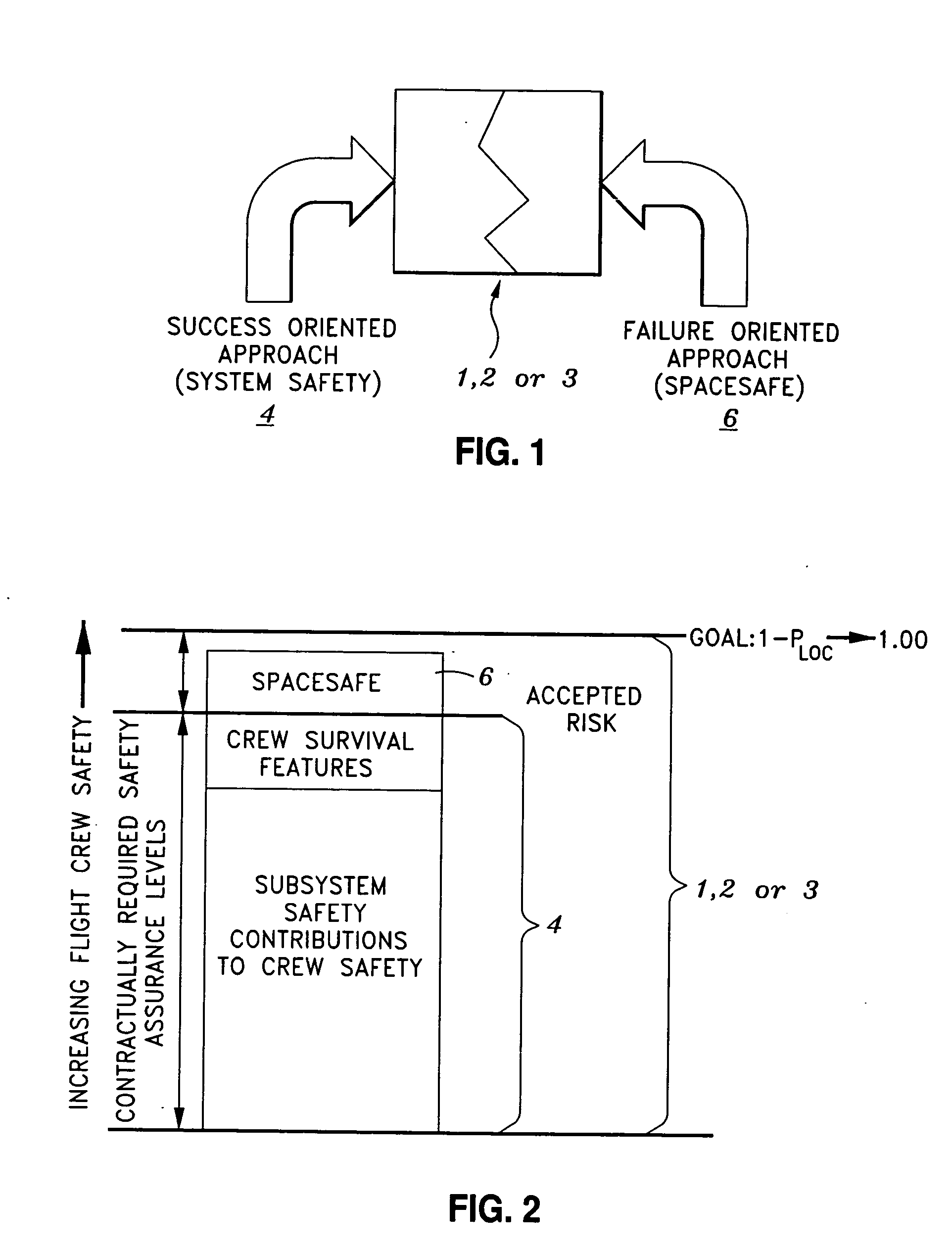
[0009] The present invention provides a means for improving the survival rate of astronaut operating crews in the event of a catastrophic subsystem failure. The process is intended to complement other engineering activities (System Safety and Crew Survival), which are also intended to provide safety for the flight crews during nominal and expected flight operations. One aspect of the present invention is that it provides a process which takes a failure-oriented approach towards providing the maximum benefit for crew survival. Furthermore, the present invention is not limited to a specific Safety Critical Subsystem, nor is limited to specified sets of causal factors, nor is limited to the operational system itself.
[0012] The SPACESAFE Process is initiated by the identification of the Safety Critical Subsystems on of the space vehicle operating system. These Safety Critical Subsystems will be identified as a normal part of the System Safety process to analyze and assure that required safety assurance levels are met by the total system. The System Safety process will then further decompose the Safety Critical Subsystems to identify all causal factors that can result in hazards to the flight crew and mitigate those causal factors that cause the system to not meet safety assurance levels.

Problems solved by technology

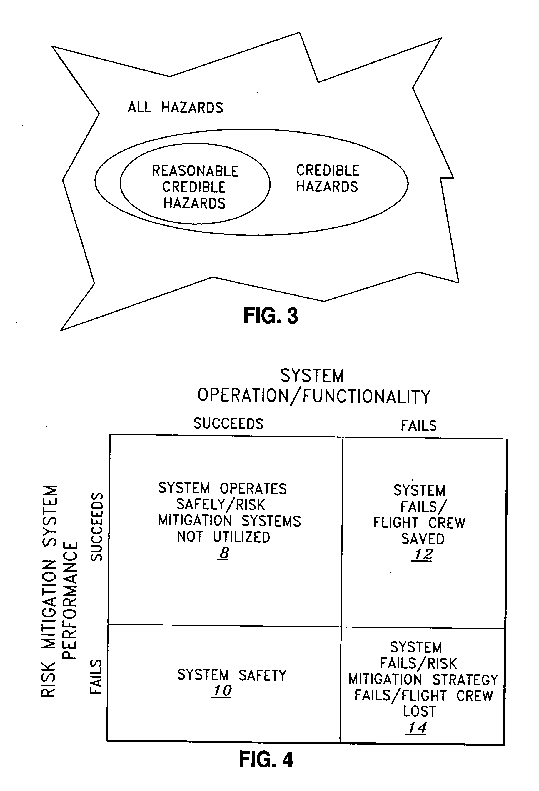
As previously discussed, the SPACESAFE process operates under the assumption that safety critical subsystems have failed and that catastrophic or critical hazards are imminent.
Typical system safety efforts and analyses (i.e. prior art) are a success-oriented approaches to the safety assessment of systems, and are limited to specific Safety Critical Subsystem analysis.

Method used


Image

  • Method of evaluation of space systems for safety assurance and residual risk to flightcrew
  • Method of evaluation of space systems for safety assurance and residual risk to flightcrew
  • Method of evaluation of space systems for safety assurance and residual risk to flightcrew

Examples


first embodiment

the Process in Context of the System Safety Program

[0043] A first exemplary embodiment of the SPACESAFE process 1 is flow diagrammed in FIG. 7. At 70, hazards are identified. At 72, Safety Critical Subsystems are identified. At 74, safety critical failure modes and effects are identified. At this breakpoint, System Safety now proceeds with the assessment of risk at the subsystem level and collects the risk calculation to the top level for determination of contractual or Statement of Work (SOW) compliance and verification of the risk assessment by test. Any verification failures or analytical failures are resolved through design or procedural changes until contract or SOW compliance, at a minimum, is achieved. At 78, risk mitigation strategies are evaluated and ranked, with respect to hardware changes 80, software changes 82, procedural changes 84, and other changes 86. At 88, cost, schedule, and risk reduction benefit [% decrease in probability of loss of crew (PLOC)] are evaluated ...

second embodiment

a Process in Context of the System Safety Program

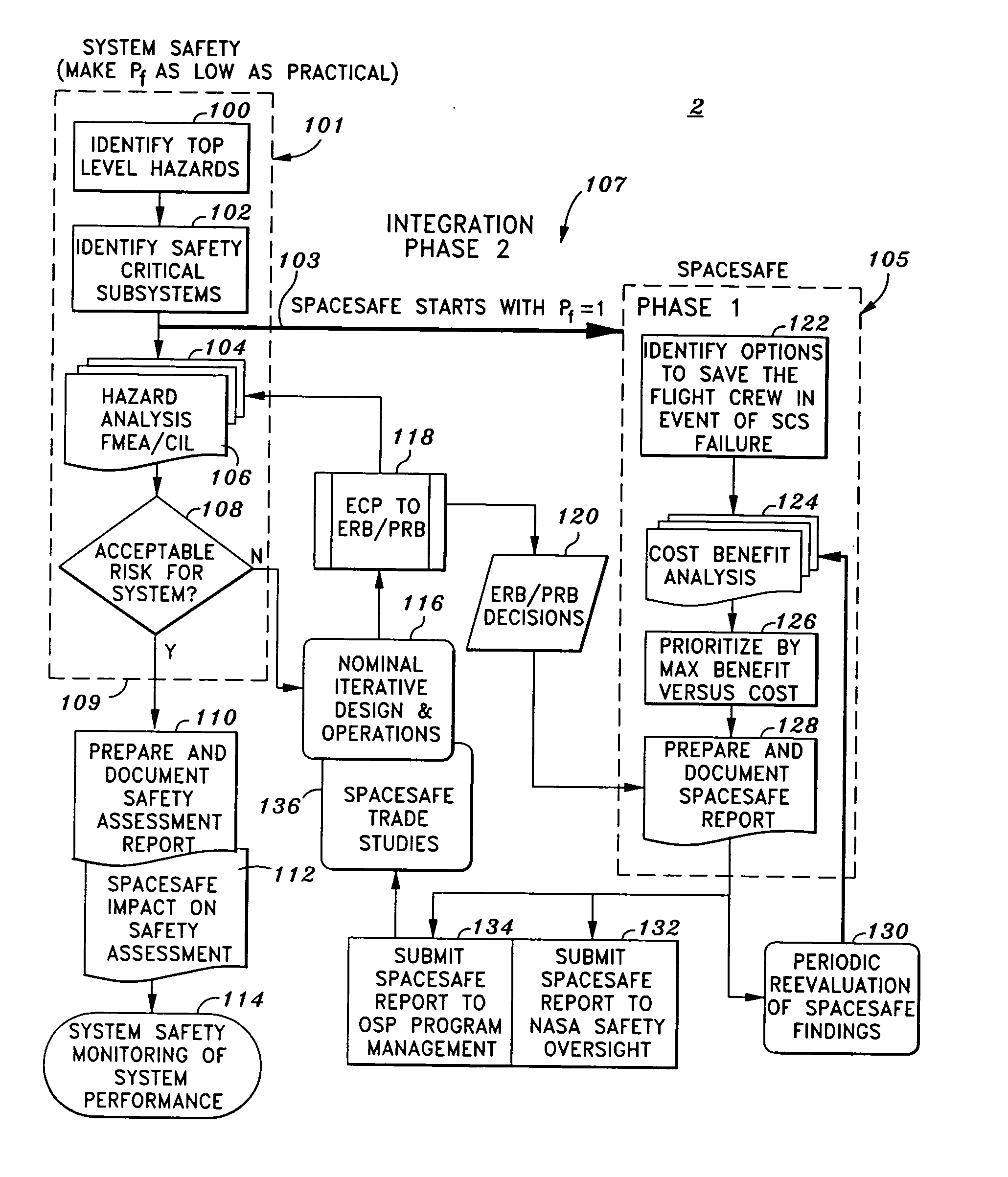
[0044] A second exemplary embodiment of the SPACEBASE process 2 is flow diagrammed in FIG. 8. This process 2 may generally be broken down into several sequences / and or phases, including a “System Safety” phase 101, SPACESAFE “Phase 1”105, and a Integration “Phase 2”107 which integrates the System Safety phase with SPACESAFE “Phase 1”.

[0045] Steps 100 through 109 represent the System Safety sequence 101. It is noted that with the System Safety process, Pf, the probability of failure, is made as low as practical. At 100, top level hazards are identified. At 102, Safety Critical Subsystems are identified. At 104, a hazard analysis is performed via a Failure Mode Effect Analysis (FMEA) and / or a Critical Items List. At 106, it is determined whether the hazard analysis from 104 is an acceptable risk for the system? If no at 108, nominal iterative design and operations are considered at 116. If yes at 109, document safety assessment reports...

third embodiment

a Process in Context of the System Safety Program

[0048] A third exemplary embodiment of the SPACEBASE process 3 is flow diagrammed in FIG. 9. This process 3 may generally be broken down into various sequences / and or phases, including “Phase 1” at 141, “Phase 2” at 161, Phase 3” at 175, and “Phase 4” at 179.

[0049] Before “Phase 1” at 141 is initiated, at 140 the system is baselined and Safety Critical Subsystems (SCS) are identified. Here the SCS list is received from the System Safety function. Moreover, it is assumed the probability of failure, Pf=1 for Safety Critical Subsystems. It is noted that the analysis is performed on each SCS. Once the system is baselined and SCS are identified, Phase 1 is initiated at 142.

[0050] At 142 risk mitigation options are identified. Here, brainstorming occurs, including structured discussion with discipline experts sufficient to address the loss of SCS functionality. Also, discipline experts outside the program design influence are selected (in...


PUM


Abstract

A process for evaluating space systems for safety assurance and residual risk to the flight crew. The process includes a success oriented System Safety phase which attempts to reduce the probability of failure with respect to the loss of a crew member as low as practical; a failure oriented SPACESAFE phase which assumes that at least one Safety Critical Subsystem has failed and attempts to engineer a risk mitigation design minimize adverse effects on the crew; and an Integration phase which complimentary integrates the System Safety phase with the SPACESAFE phase. Such process allows for increased flight crew safety by minimizing risk of a failures that contribute to loss of a crew member.

Description

STATEMENT RE: FEDERALLY SPONSORED RESEARCH / DEVELOPMENT [0001] The present invention was developed under U.S. Government Contract No. NAS8-01100CROSS-REFERENCE TO RELATED APPLICATIONS [0002] Not Applicable BACKGROUND OF THE INVENTION [0003] 1. Field of the Invention [0004] The present invention relates to processes used to evaluate manned space systems for safety assurance and residual risk to flight crew. More specifically, the present invention relates to a process which utilizes a success-oriented System Safety process and a complementary failure-oriented approach (a.k.a. SPACESAFE) as a means for improving the survival of astronaut crews in the event of a catastrophic system failure. [0005] 2. Background of the Invention [0006] Throughout the history of manned space flight, various safety, quality, and reliability principles expressed in processes, analyses, and / or algorithms have been implemented to increase mission success rate and to ensure the ultimate safety of the flight cr...

Claims


Application Information

Patent Timeline
IPC IPC(8): B64G1/12B64G99/00B64G1/52F02K1/00
CPCB64G1/52B64G1/12
Inventor GALUTIA, BARRY CLIFFORDYOUNG, DOUG HAROLD
Owner NORTHROP GRUMAN CORP
Learn More