
Microprocessor apparatus and method for modular exponentiation

a microprocessor and modular technology, applied in the field of microelectronics, can solve the problems of inability to effectively stem the tide of computer information compromise, the speed of encryption and decryption operations is excruciatingly slow, and the effect of spies and government agencies is not clear

Active Publication Date: 2005-11-17
VIA TECH INC
View PDF9 Cites 14 Cited by
  • Summary
  • Abstract
  • Description
  • Claims
  • Application Information

AI Technical Summary

Benefits of technology

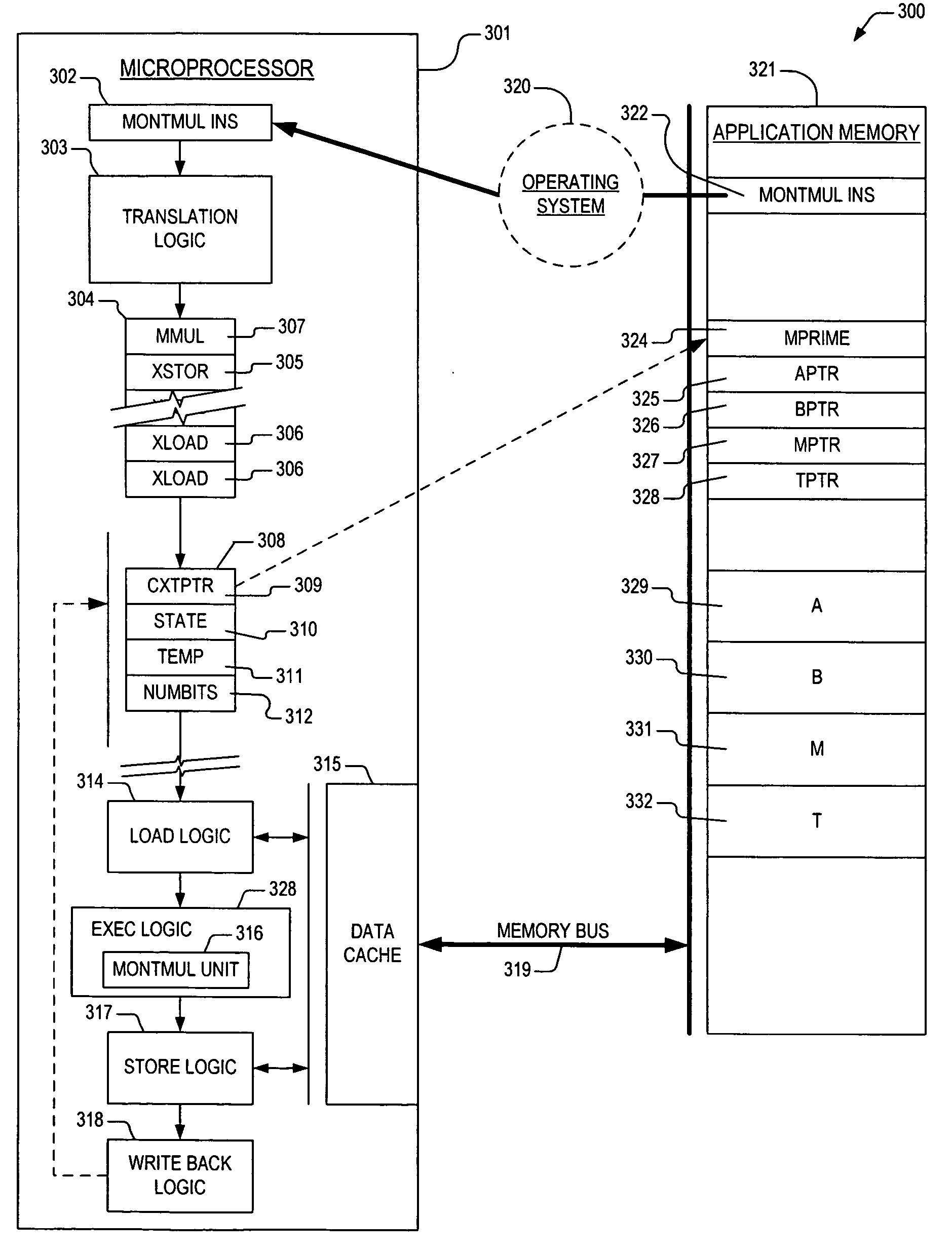
The present invention provides a better way to do modular multiplication. It includes a machine that can translate a Montgomery multiplication instruction into a sequence of smaller instructions and perform them to get the final result. This makes the process faster and more efficient.

Problems solved by technology

These cryptographic programs typically scrambled and unscrambled the output data that was stored as files on mass storage devices.
Yet, none of these responses has proved to be effective at stemming the tide of computer information compromise.
Consequently, what was once the exclusive concern of governments, financial institutions, the military, and spies has now become a significant issue for the average citizen who reads their email or accesses their checking account transactions from their home computer.
Although this class of cryptographic algorithms enjoys widespread use today, encryption and decryption operations are excruciatingly slow—even on small amounts of data.
But any cryptosystem that employs a symmetric key technique is subject to compromise any time the key is compromised.
Thus, the distribution and protection of symmetric keys is very problematic.
One skilled will also appreciate that while multiplication of two large integers is not a trivial task for a present day computer, trial division is significantly more complicated.
Most, if not all of these devices, and others, utilize a microprocessor as the central processor therein, and thus do not provide for the addition of dedicated RSA computational hardware.

Method used


Image

  • Microprocessor apparatus and method for modular exponentiation
  • Microprocessor apparatus and method for modular exponentiation
  • Microprocessor apparatus and method for modular exponentiation

Examples


Embodiment Construction

[0025] The following description is presented to enable one of ordinary skill in the art to make and use the present invention as provided within the context of a particular application and its requirements. Various modifications to the preferred embodiment will, however, be apparent to one skilled in the art, and the general principles defined herein may be applied to other embodiments. Therefore, the present invention is not intended to be limited to the particular embodiments shown and described herein, but is to be accorded the widest scope consistent with the principles and novel features herein disclosed.

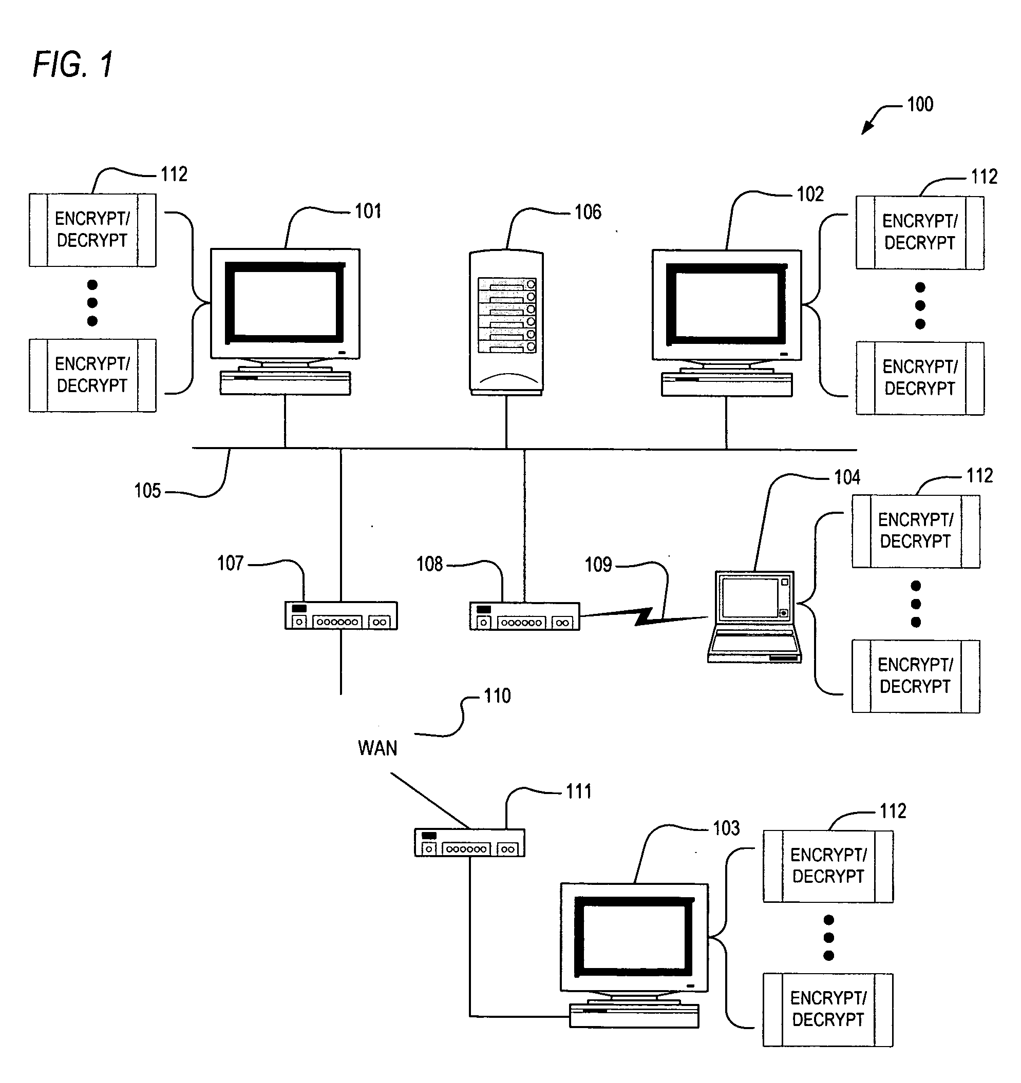
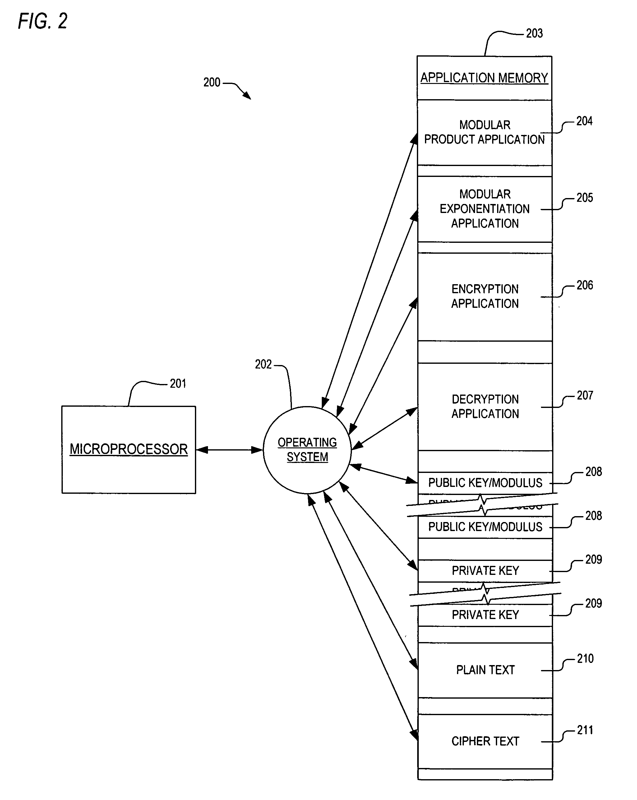
[0026] In view of the above background discussion on modular exponentiation operations and associated techniques employed within present day computer systems, a detailed discussion of these techniques and their limitations will now be provided with reference to FIGS. 1-2. Following this, the present invention will be discussed with reference to FIGS. 3-6. The present inventio...


PUM


Abstract

A technique is provided for performing modular multiplication. In one embodiment, an apparatus in a microprocessor is provided for accomplishing modular multiplication operations. The apparatus includes translation logic and execution logic. The translation logic receives a Montgomery multiplication instruction from a source therefrom, where the Montgomery multiplication instruction prescribes generation of a Montgomery product. The translation logic translates the Montgomery multiplication instruction into a sequence of micro instructions specifying sub-operations required to accomplish generation of the Montgomery product. The execution logic is operatively coupled to the translation logic. The execution logic receives the sequence of micro instructions, and performs the sub-operations to generate the Montgomery product.

Description

CROSS-REFERENCE TO RELATED APPLICATIONS [0001] This application claims the benefit of the following U.S. Provisional Applications, each of which is herein incorporated by reference for all intents and purposes. SER.FILINGNO.DATETITLE60 / 571124May 14, 2004MONTGOMERY MULITPLIER(CNTR.2237)MECHANSIM60 / 582422Jun. 24, 2004SECURITY APPLICATION NOTE(CNTR.2253)60 / 582696Jun. 24, 2004MONTGOMERY MULTIPLIER(CNTR.2254)PROGRAMMING GUIDEBACKGROUND OF THE INVENTION [0002] This invention relates in general to the field of microelectronics, and more particularly to an apparatus and method in a microprocessor or other device for performing modular multiplication. DESCRIPTION OF THE RELATED ART [0003] An early computer system operated independently of other computer systems in the sense that all of the input data required by an application program executing on the early computer system was either resident on that computer system or was provided by an application programmer at run time. The application p...

Claims


Application Information

Patent Timeline
Patent Type & Authority Applications(United States)
IPC IPC(8): G06F7/38G06F9/302G06F9/318
CPCG06F7/728G06F9/3017G06F9/30174G06F9/3001
Inventor CRISPIN, THOMAS A.HENRY, G. GLENNPARKS, TERRY
Owner VIA TECH INC
Learn More