Apparatus for drawing an optical fiber and method for controlling feed speed of an optical fiber preform

a technology of optical fiber and preform, which is applied in the direction of glass making apparatus, instruments, manufacturing tools, etc., can solve the problems of increasing the melting rate of the preform, sharply increasing the drawing speed, and melting rate, so as to prevent an abrupt change of the feed speed

Inactive Publication Date: 2005-11-24
SAMSUNG ELECTRONICS CO LTD
View PDF0 Cites 2 Cited by
  • Summary
  • Abstract
  • Description
  • Claims
  • Application Information

AI Technical Summary

Benefits of technology

[0023] Preferably, during the step of adding or subtracting the modification value of the preform feed speed to or from the target speed, when the modification value of the preform feed speed is in a predetermined range from a negative predetermined value to a positive predetermined value, the present feed speed is changed by adding the negative or positive predetermined value to the present feed speed, and processes of changing the present feed speed and determining the range of modification value are repeated at intervals of a predetermined time until the feed speed reaches the target speed, so as to prevent an abrupt change of the feed speed.

Problems solved by technology

The accumulation of heat causes changes in the melting rate of the preform, such that it increases the melting rate of the preform.
However, as the exhaustion continues, the drawing speed sharply increases.
Therefore, when the optical-fiber outer diameter is controlled using only the capstan (as in the prior art), the following problems occur.
Firstly, the optical fiber increasingly becomes less and less straight, thereby raising the defective rate of the optical characteristic of the optical fiber.
Secondly, the variation of the drawing speed leads to an increase of the non-uniformity in the outer diameter of the optical fiber or the protection coating.
Thirdly, continuous observation is needed to control the feed speed, and therefore the utilization of working-manpower is not efficient.

Method used


Image

  • Apparatus for drawing an optical fiber and method for controlling feed speed of an optical fiber preform
  • Apparatus for drawing an optical fiber and method for controlling feed speed of an optical fiber preform
  • Apparatus for drawing an optical fiber and method for controlling feed speed of an optical fiber preform

Examples


Embodiment Construction

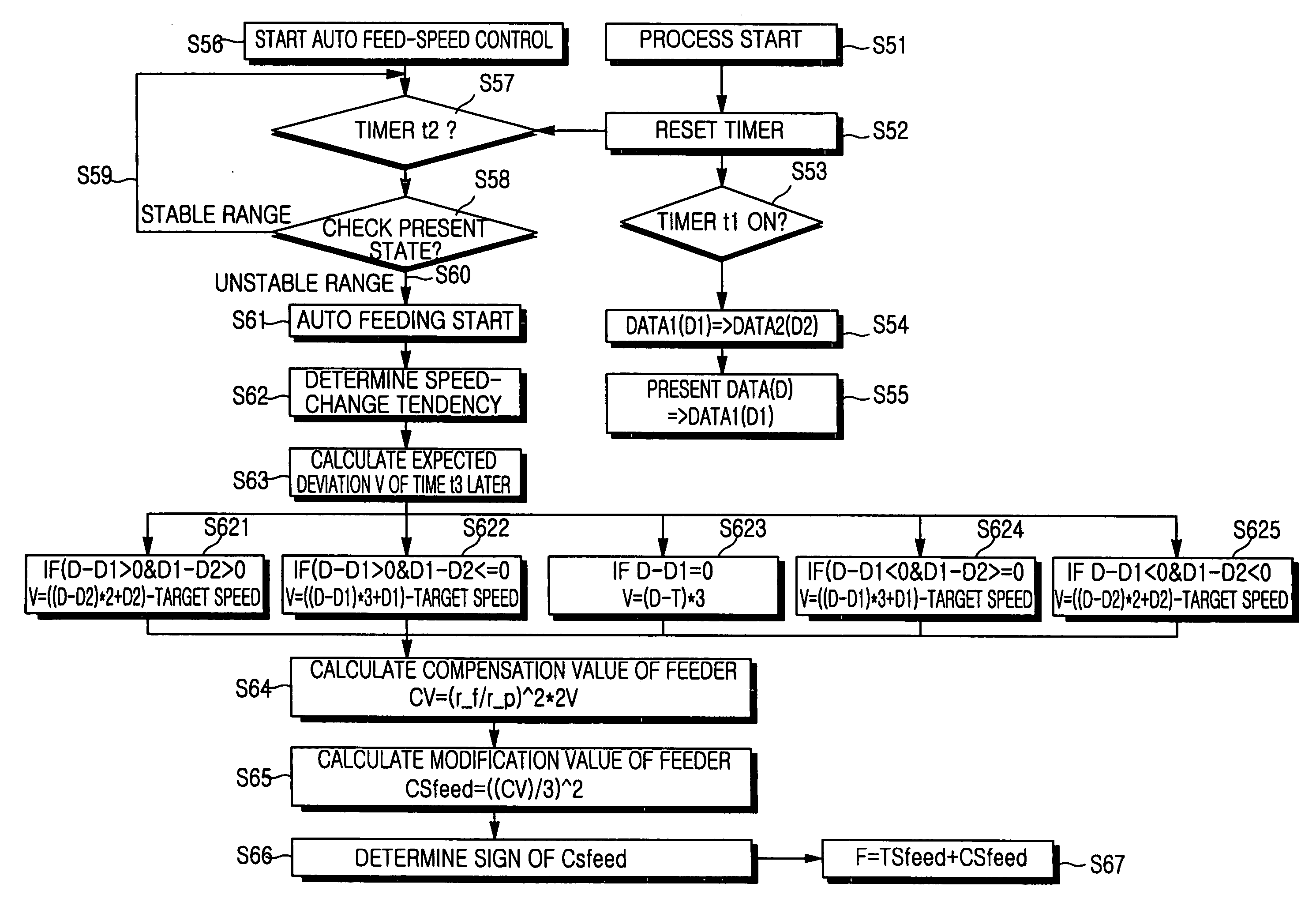
[0034] Now, a preferred embodiment of the present invention will be described in detail with reference to FIGS. 5 to 8. In the drawings, the same or similar elements are denoted by the same reference numerals even though they are depicted in different drawings. For the purposes of clarity and simplicity, a detailed description of known functions and configurations incorporated herein will be omitted when it may make the subject matter of the present invention unclear.

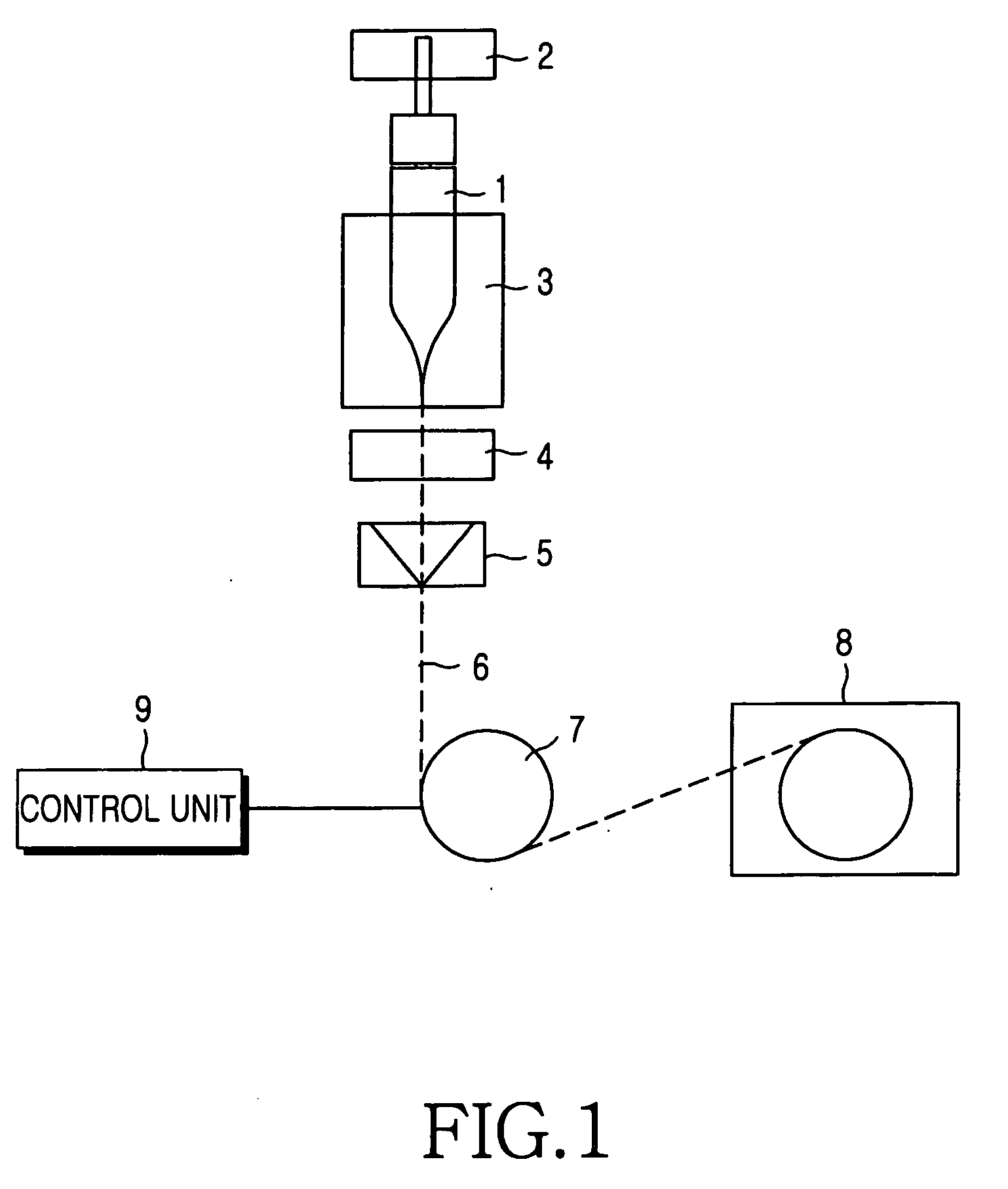
[0035]FIG. 5 is a view illustrating signals flowing in an apparatus for drawing an optical fiber according to the present invention.

[0036] Similar to the prior art, the apparatus includes a melting furnace, a preform feeder, a measurement unit of an optical-fiber outer diameter, a coating unit, a capstan, a spool, and a control unit. The following description will be made concentrating on the control unit.

[0037] As shown in FIG. 5, the control unit 10 receives a signal representing the drawing speed of an optical fib...


PUM

PropertyMeasurementUnit
feed speedaaaaaaaaaa
drawing speedaaaaaaaaaa
speedaaaaaaaaaa

Abstract

An apparatus for drawing an optical fiber and a method for controlling the feed speed of an optical fiber preform whereby the drawing speed of an optical fiber is stabilized to keep the size of the outer diameter uniform. The capstan speed is determined based on the outer diameter of the optical fiber. When the capstan speed is out of a target speed range, the preform feed speed is controlled to bring the capstan speed into the target range. A control unit includes a calculation unit for receiving a drawing speed signal output from the capstan and calculating a feed speed of the perform. The control unit regulates the outer diameter of the optical fiber by regulating the speed of the capstan according to a signal received from the outer diameter measurement unit indicating a change in the outer diameter of the optical fiber.

Description

CLAIM OF PRIORITY [0001] This application claims priority to an application entitled “Apparatus for drawing an optical fiber and method for controlling the feed speed of an optical fiber perform,” filed in the Korean Intellectual Property Office on Jul. 29, 2002 and assigned Serial No. 2002-44754, the contents of which are hereby incorporated by reference. BACKGROUND OF THE INVENTION [0002] 1. Field of the Invention [0003] The present invention relates to an apparatus for drawing an optical fiber and a method for controlling the feed speed of an optical fiber. More particularly, the method relates to a preform whereby the drawing speed of the optical fiber is stabilized to keep uniform the outer diameter of the optical fiber. [0004] 2. Description of the Related Art [0005] Generally, when an optical fiber is drawn, the length of the outer diameter of the optical fiber is controlled using its drawing speed. FIG. 1 is a view showing the basic configuration of an apparatus for drawing ...

Claims


Application Information

Patent Timeline
Patent Type & Authority Applications(United States)
IPC IPC(8): G02B6/00C03B37/025C03B37/027C03B37/12
CPCC03B37/0253C03B2205/44C03B2205/40C03B37/027
Inventor LEE, MYUNG-SOPJUNG, KI-TAEPARK, JAE-HONG
Owner SAMSUNG ELECTRONICS CO LTD
Why Eureka
Try Eureka