Integrated metal processing facility

a metal processing facility and integrated technology, applied in the direction of heat treatment equipment, manufacturing tools, furnaces, etc., can solve the problems of increasing the cost of heat treatment process, unable to address the problem of castings being subjected to the ambient environment, and reducing the time required for heat treatment of castings, so as to achieve enhanced or reduced overall processing and heat treatment time for castings.

Inactive Publication Date: 2005-11-24
CONSOL ENG
View PDF99 Cites 10 Cited by
  • Summary
  • Abstract
  • Description
  • Claims
  • Application Information

AI Technical Summary

Benefits of technology

[0012] By arresting the cooling of the castings and thereafter maintaining the castings at a temperature that is substantially at or above the process control temperature for the metal of the castings, the time required for the heat treatment of the castings can be significantly reduced as the castings can be rapidly brought up to a solution heat treatment temperature within a relatively short period of time after their introduction into the heat treatment station or furnace. Accordingly, the output of the pouring station for the castings can be increased, and thus the overall processing and heat treatment times for the castings can be enhanced or reduced.

Problems solved by technology

As a result, the castings tend to begin to rapidly cool down from a molten or semi-molten temperature.
As a consequence, however, the longer the heat treatment time and the more heat required to properly and completely heat treat the castings, the greater the cost of the heat treatment process and the greater the waste of heat and energy.
The problem with this system is that it still fails to address the problem of the castings being subjected to the ambient environment, which generally is at temperatures much lower than the desired process control temperature of the castings, both during the transfer of the castings to a collection basket and while the castings sit in the basket awaiting introduction into the heat treatment furnace.
Thus, moving the castings from pouring to heat treatment too quickly can disrupt the formation of the castings and prevent them from properly solidifying.

Method used


Image

  • Integrated metal processing facility
  • Integrated metal processing facility
  • Integrated metal processing facility

Examples


Embodiment Construction

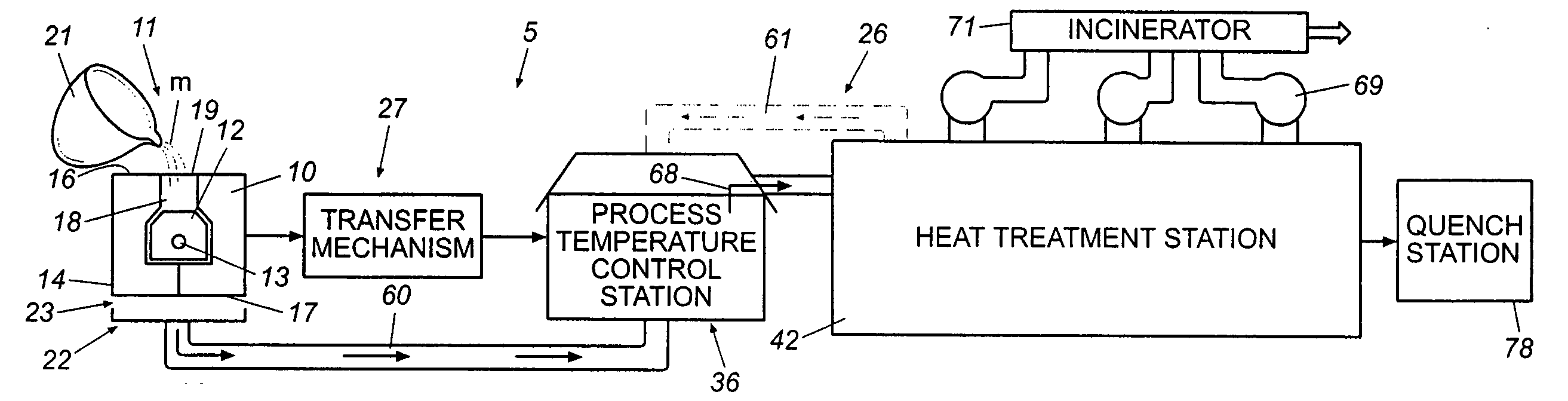
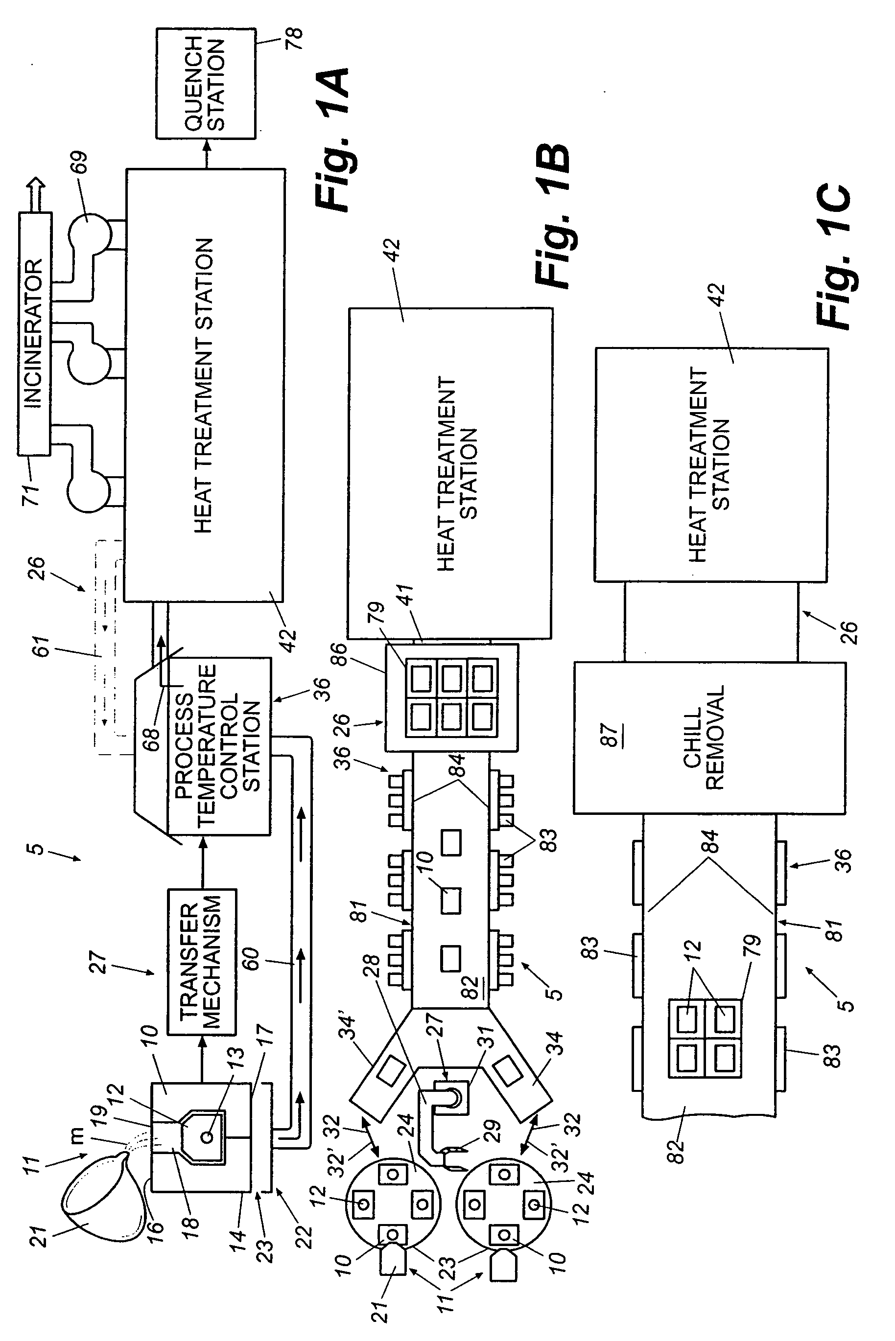
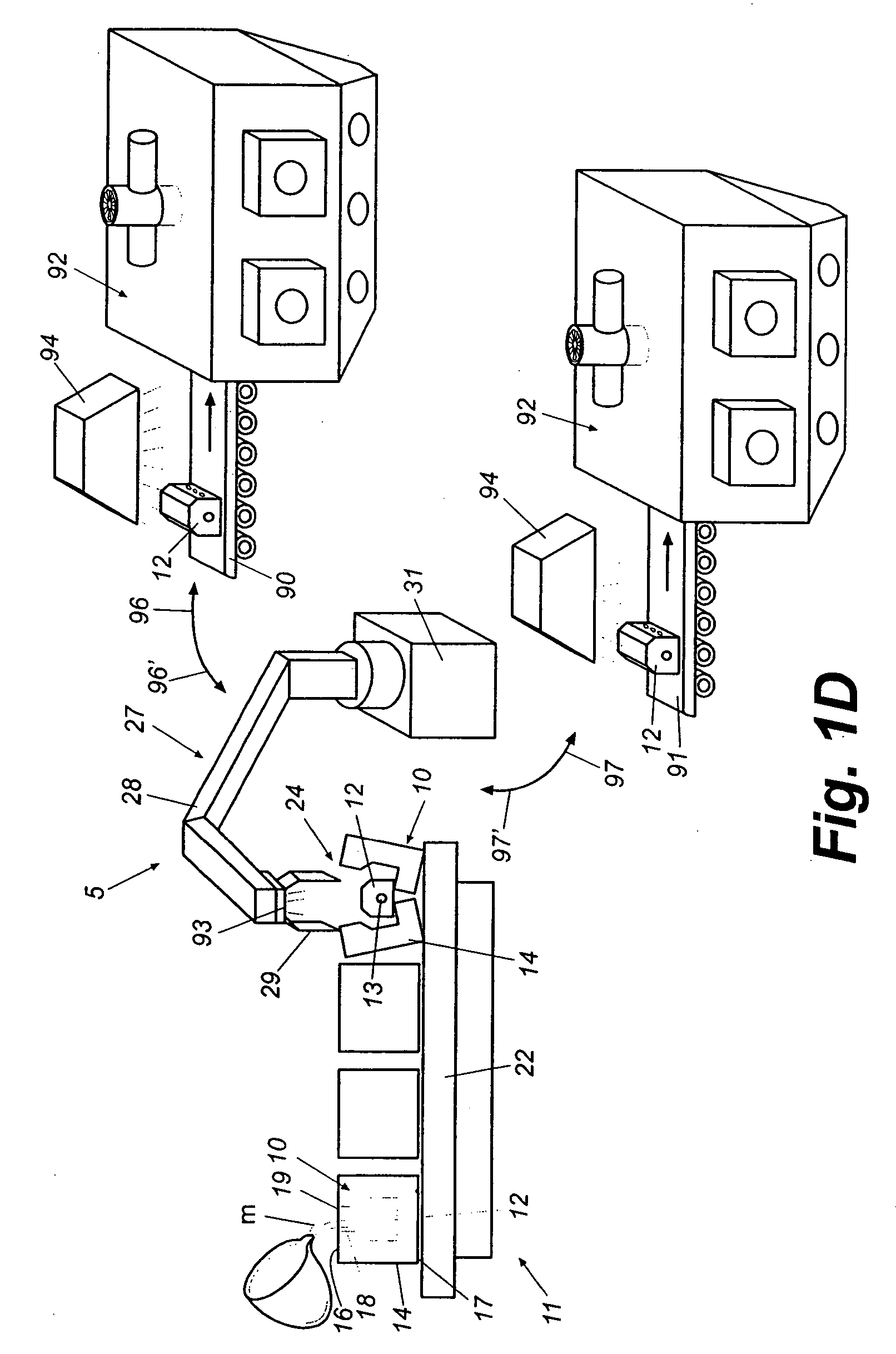
[0025] Referring now in greater detail to the drawings in which like numerals refer to like parts throughout the several views, FIGS. 1A-3 schematically illustrate an integrated metal processing facility or system 5 and method of processing metallurgical castings. Metal casting processes are generally well known to those skilled in the art and a traditional casting process will be described only briefly for reference purposes. It will also be understood by those skilled in the art that the present invention can be used in any type of casting process, including metal casting processes for forming aluminum, iron, steel and / or other types of metal and metal alloy castings. The present invention thus is not and should not be limited solely for use with a particular casting process or a particular type or types of metals or metal alloys.

[0026] As illustrated in FIG. 1A, typically, a molten metal or metallic alloy M is poured into a die or mold 10 at a pouring or casting station 11 for f...


PUM

PropertyMeasurementUnit
temperatureaaaaaaaaaa
temperaturesaaaaaaaaaa

Abstract

An integrated metal processing facility in which molten metal is poured into a series of molds at a pouring station to form metal castings, which are then transferred to a heat treatment line. Prior to introduction of the castings into a heat treatment station of the heat treatment line, the castings are subjected to heating sufficient to arrest cooling of the castings at or above a process control temperature for the metal thereof.

Description

CROSS REFERENCE TO RELATED APPLICATION [0001] This application claims the benefit of U.S. Provisional Application Ser. No. 60 / 266,357, filed Feb. 2, 2001.TECHNICAL FIELD [0002] This invention generally relates to metallurgical casting and treatment processes, and more specifically to an integrated metal processing facility and method of heat treating castings. BACKGROUND OF THE INVENTION [0003] Traditionally, in conventional processes for forming metal castings, a mold such as a metal die or sand mold having an interior chamber with the exterior features of a desired casting defined therein, is filled with a molten metal. A sand core that defines interior features of the casting is received and or positioned within the mold to form the interior detail of the casting as the molten metal solidifies about the core. After the molten metal of the casting has solidified, the casting generally is thereafter moved to a treatment furnace(s) for heat treatment of the castings, removal of sand...

Claims


Application Information

Patent Timeline
Patent Type & Authority Applications(United States)
IPC IPC(8): B22D29/00B22D45/00B22D30/00C21D1/00C21D1/52C21D1/53C21D9/00C22F1/00
CPCB22D29/00B22D29/003B22D47/00C22F1/00C21D1/53C21D9/0068C21D11/00C21D1/52
Inventor CRAFTON, SCOTT P.CRAFTON, PAUL M.LEWIS, JAMES L. JR.FRENCH, IAN
Owner CONSOL ENG
Why Eureka
Try Eureka