
Device and method for manufacturing membrane-electrode assembly of fuel cell

a technology of fuel cell and assembly device, which is applied in the direction of cell components, sustainable manufacturing/processing, and final product manufacturing, etc., can solve the problems of catalyst electrode layer damage, reduce and prevent damage of the catalyst electrode layer. , the effect of reducing the heat treatment duration of the membrane-electrode assembly

Active Publication Date: 2020-06-02
HYUNDAI MOTOR CO LTD +1
View PDF26 Cites 0 Cited by
  • Summary
  • Abstract
  • Description
  • Claims
  • Application Information

AI Technical Summary

Benefits of technology

Improves the interface bonding force between the electrolyte membrane and catalyst electrode layer, reduces heat treatment time, prevents damage to the catalyst electrode layer, and enhances the durability and productivity of the membrane-electrode assembly.

Problems solved by technology

However, the heat treatment is performed while the membrane-electrode assembly is exposed in high temperature during an extended duration since a heat transmission into the electrolyte membrane is not smooth.
In other words, as the heat treatment is performed while the membrane-electrode assembly is exposed in high temperature during an extended duration, a damage of the catalyst electrode layer occurs, because of the duration required for the heat treatment and productivity of the membrane-electrode assembly deteriorates.

Method used


Image

  • Device and method for manufacturing membrane-electrode assembly of fuel cell
  • Device and method for manufacturing membrane-electrode assembly of fuel cell
  • Device and method for manufacturing membrane-electrode assembly of fuel cell

Examples


Embodiment Construction

[0032]The present disclosure will be described more fully hereinafter with reference to the accompanying drawings, in which exemplary embodiments of the disclosure are shown. As those skilled in the art would realize, the described embodiments may be modified in various different ways, all without departing from the spirit or scope of the present disclosure. In order to clarify the present disclosure, parts that are not connected with the description will be omitted, and the same elements or equivalents are referred to with the same reference numerals throughout the specification. Also, the size and thickness of each element are arbitrarily shown in the drawings, but the present disclosure is not necessarily limited thereto, and in the drawings, the thickness of layers, films, panels, regions, etc., are exaggerated for clarity.

[0033]It will be understood that, although the terms first, second, etc. may be used herein to describe various elements, these elements should not be limited...


PUM

PropertyMeasurementUnit
shapeaaaaaaaaaa
circumferenceaaaaaaaaaa
ultrasonic wave vibrationaaaaaaaaaa

Abstract

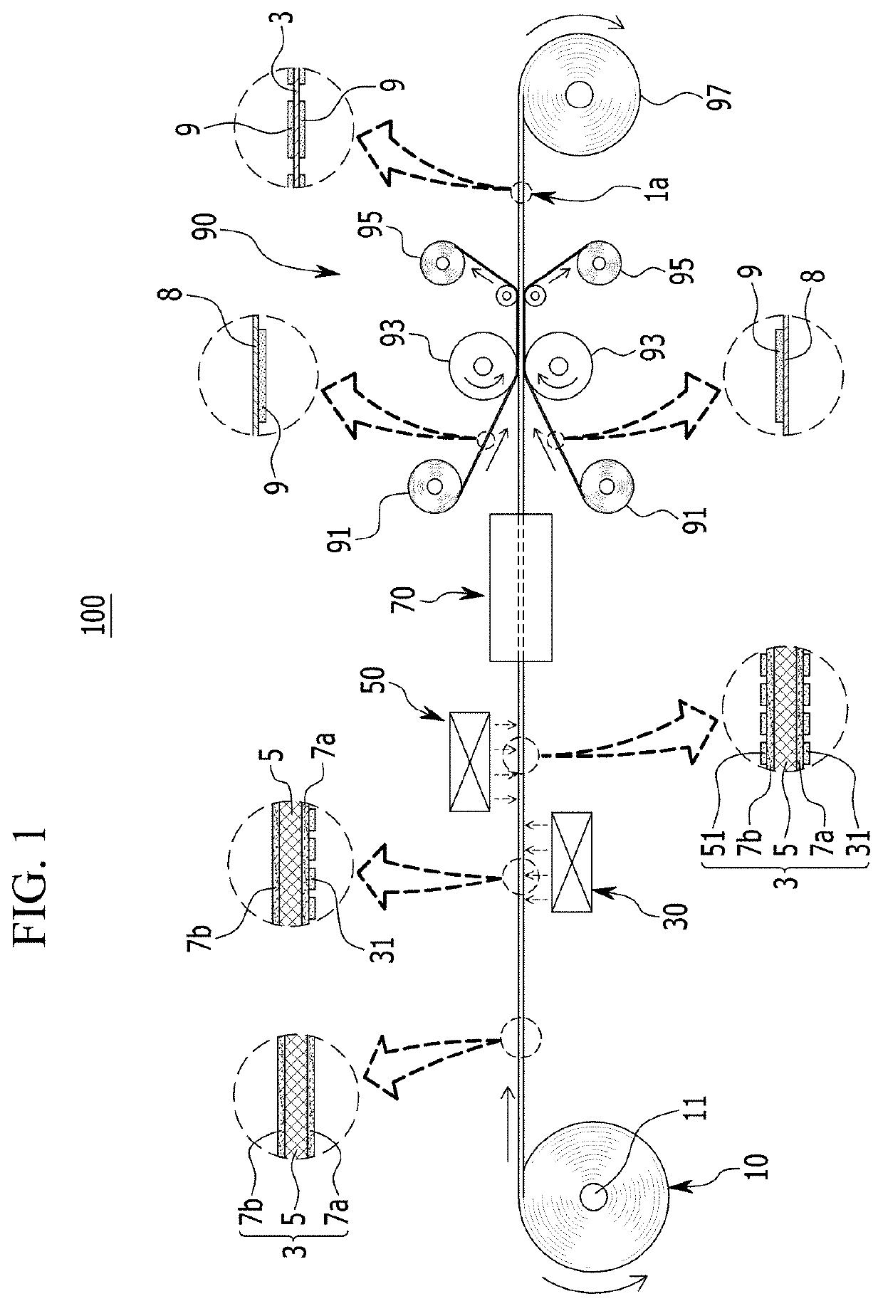
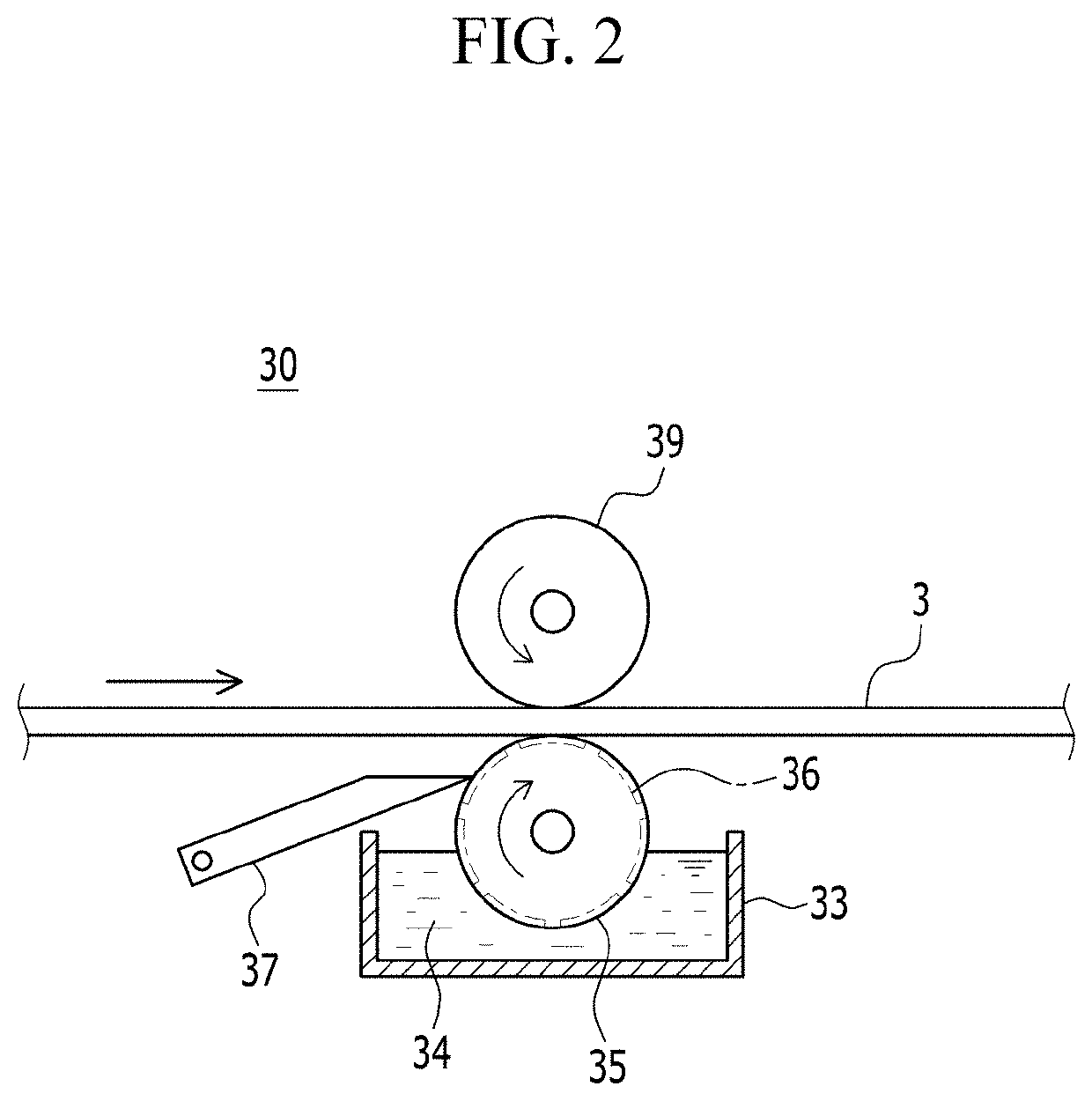
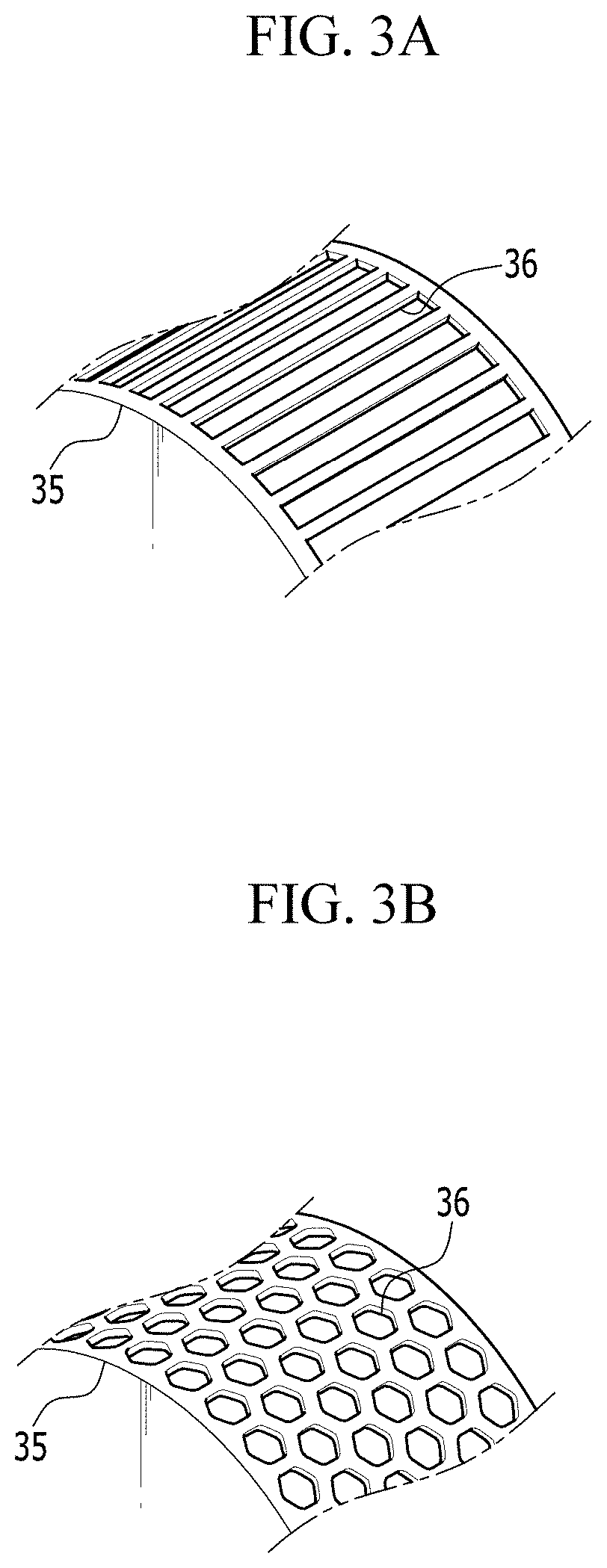
A manufacturing device of a membrane-electrode assembly for a fuel cell is provided. The manufacturing device includes an electrolyte membrane feeding unit forming a first and second ionomer bases impregnated at both surfaces of a reinforcing layer and unwinding an electrolyte membrane wound in a roll type supplied in a predetermined transporting path. A first patterning unit is disposed at a rear side of the electrolyte membrane feeding unit and patterns a first ionomer protrusion pattern layer on the first ionomer base and a second patterning unit is disposed at the rear side of the first patterning unit and patterns a second ionomer protrusion pattern layer on the second ionomer base. A transfer unit is disposed at the rear side of the second patterning unit and couples a catalyst electrode layer on the first and second ionomer protrusion pattern layers by a roll laminating method.

Description

CROSS-REFERENCE TO RELATED APPLICATION[0001]This application claims priority to and the benefit of Korean Patent Application No. 10-2017-0057946 filed in the Korean Intellectual Property Office on May 10, 2017, the entire contents of which are incorporated herein by reference.BACKGROUND(a) Field of the Disclosure[0002]The present disclosure relates to a fuel cell stack component manufacturing system, and more particularly, to a manufacturing device and a manufacturing method of a membrane-electrode assembly (MEA) for a fuel cell for manufacturing the membrane-electrode assembly of the fuel cell.(b) Description of the Related Art[0003]Generally, a fuel cell produces electricity via an electrochemical reaction between hydrogen and oxygen. The fuel cell is capable of continuously generating electricity by receiving a chemical reactant from an external source without requiring a separate charging process. The fuel cell is configured by disposing separators (e.g., separating plates or bi...

Claims


Application Information

Patent Timeline
Patent Type & Authority Patents(United States)
IPC IPC(8): H01M8/1086B32B37/00B32B38/00H01M8/0297H01M8/1004H01M4/88
CPCH01M8/0297B32B37/0053H01M8/1093H01M8/1004B32B38/145H01M4/8828H01M4/881H01M4/88B32B38/164B32B2457/18Y02P70/50Y02E60/50H01M4/8814H01M4/8896
Inventor KIM, KI HONG
Owner HYUNDAI MOTOR CO LTD
Learn More