Electrochemical sensor

Inactive Publication Date: 2005-11-24
HAJIZADEH KIAMARS +2
View PDF4 Cites 149 Cited by
  • Summary
  • Abstract
  • Description
  • Claims
  • Application Information

AI Technical Summary

Benefits of technology

[0011] A capillary inlet is constructed at one end of the sensor to draw the fluid sample into the body upon contact with the fluid sample. The capillary inlet is molded into the end of the body and is in communications with a reaction zone. This reaction zone is a channel formed in the body about the electrodes and is adapted for reacting with the fluid drawn into the body by the capillary force. While the reaction zone may be f

Problems solved by technology

Variations in the morphology of the electrode can result in very significant changes in the electrochemical signal readout.
While many advances have been made in the field of screen printing and conductive ink production, the technology still suffers from poor reproducibility of the electrode surface area, dimensional variations, thickness variations, micro-cracks, and shrinkage due to the repetitive and high temperature curing processes involved in using film printing technology.
Loss of solvent during printing is another factor

Method used


Image

  • Electrochemical sensor
  • Electrochemical sensor
  • Electrochemical sensor

Examples


first embodiment

The First Embodiment

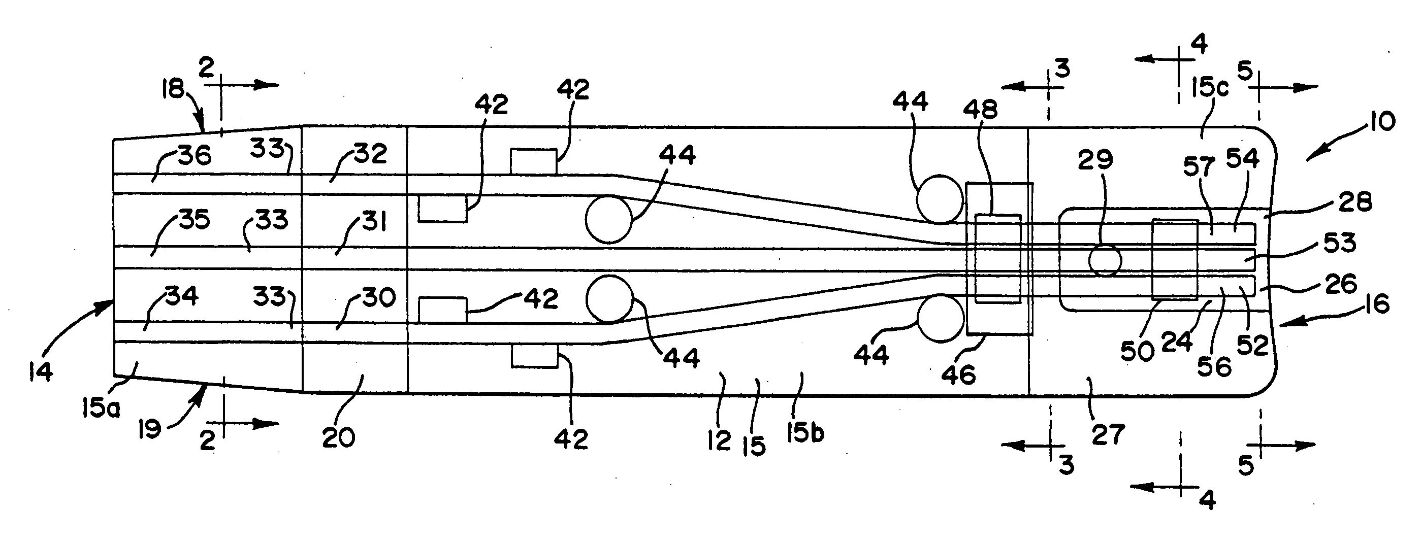
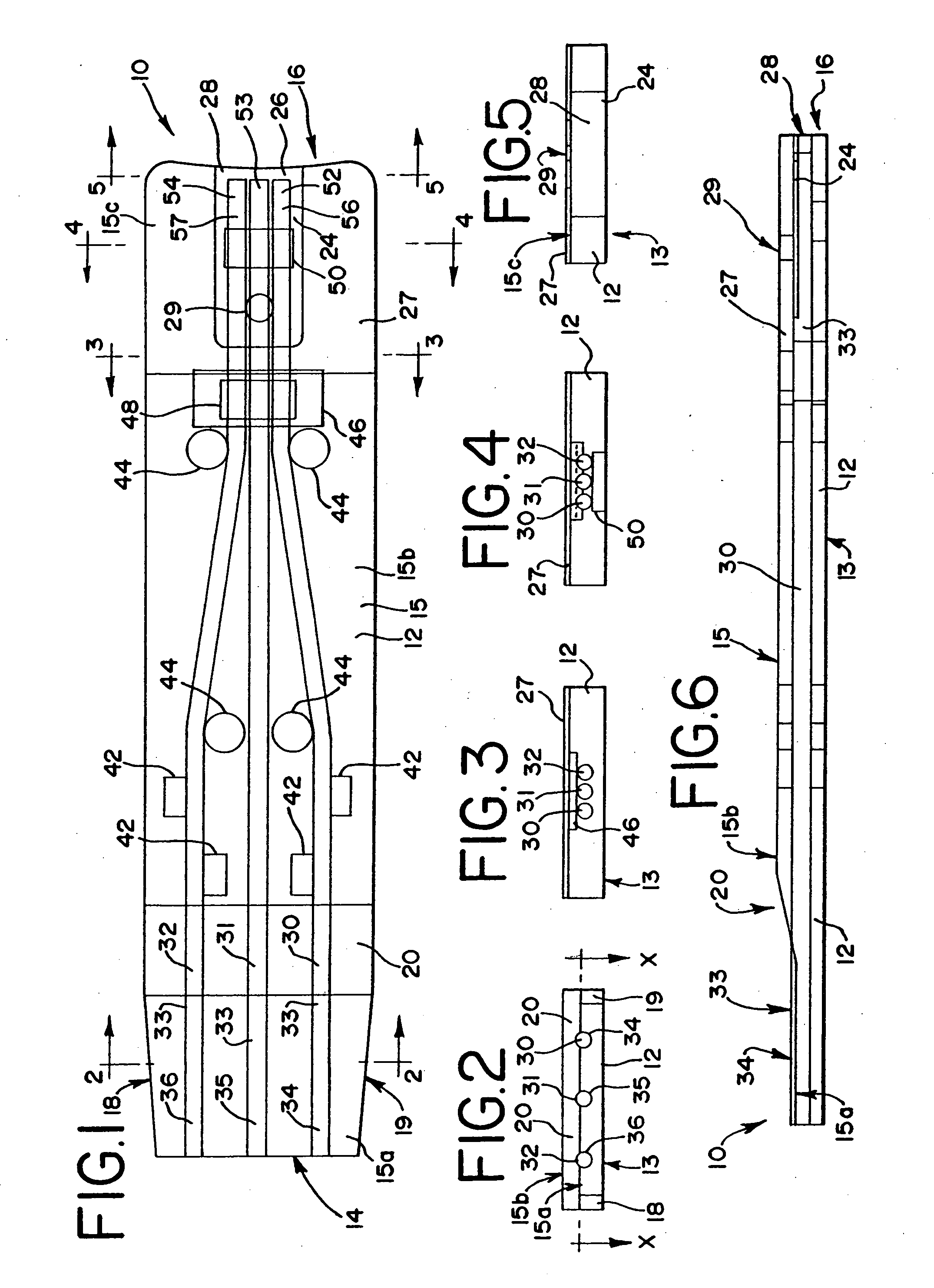
[0029] Referring to FIGS. 1-6, an electrochemical sensor in accordance with the present invention, first embodiment, is depicted. FIG. 1 shows the sensor 10 as though it were made out of clear plastic, permitting one to look inside it. As discussed herein, the internal components and hidden external components would not normally be visible looking down on the sensor 10. This rendition would be similar to a view taken along plane x-x in FIG. 2.

[0030] The sensor or test strip of the first embodiment 10 includes an injection molded plastic body 12, opaque or preferably translucent, having a meter attachment end or plug end 14 and a fluid sample receiving end 16. The body has a bottom surface 13, a top surface 15 and a tapered portion 20 connecting a first top surface 15a to a second top surface 15b, the first top surface being lower than the second top surface, and a third top surface 15c, also lower than the second top surface. The body 12 contains three spaced ap...

second embodiment

The Second Embodiment

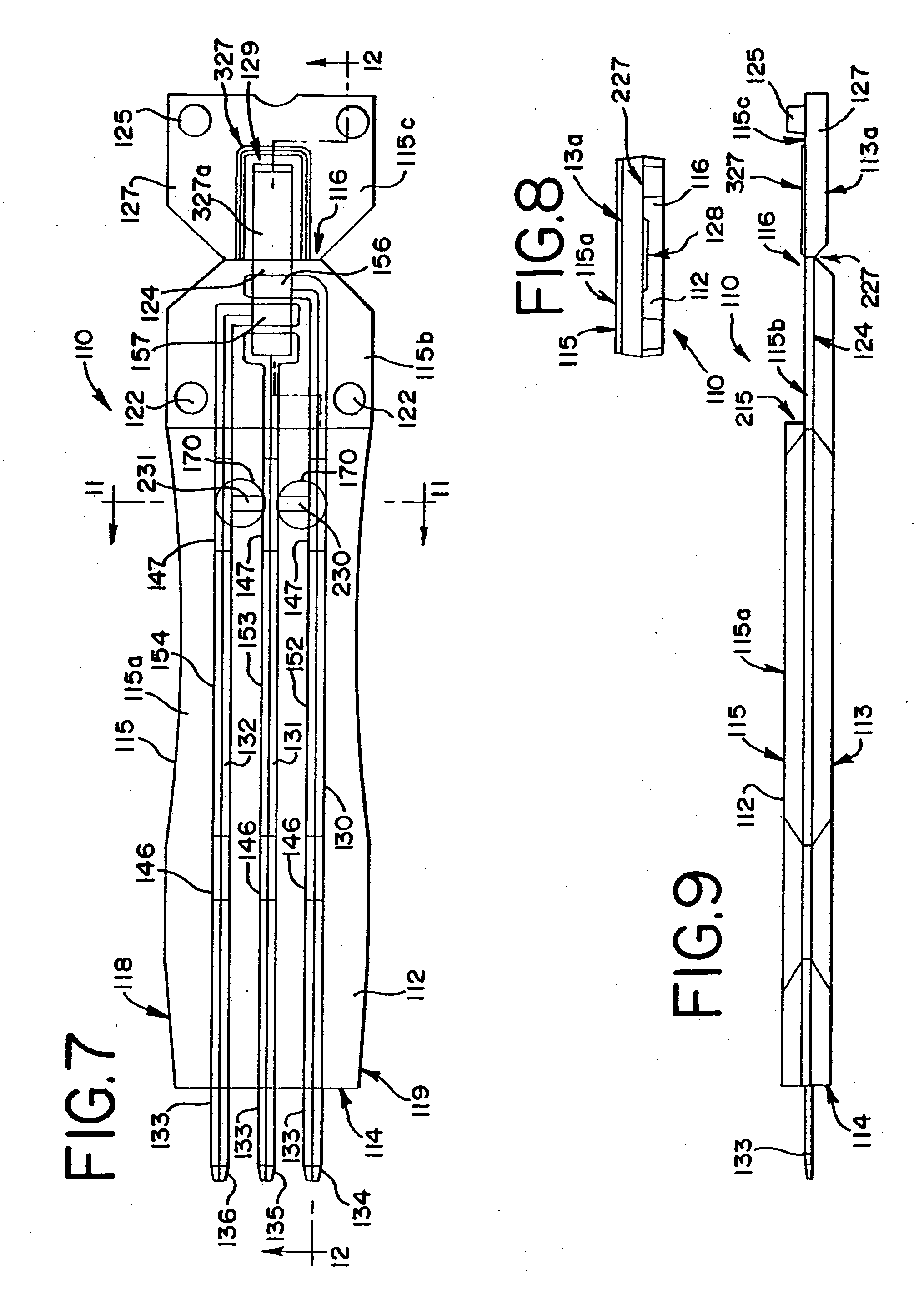
[0055] Referring to FIGS. 7-12, an electrochemical sensor in accordance with the present invention, second embodiment, is depicted. In these figures, components similar to those in the first embodiment (10) will be identified with the same reference numbers, but in the 100 series. Specifically, FIG. 7 shows the sensor 110 as though it were made out of clear plastic, permitting one to look inside it. As noted previously, the internal components and hidden external components would not normally be visible looking down on the sensor 110. The sensor of the second embodiment 110 includes a molded plastic body 112 having a meter attachment end or plug end 114 and a fluid sample receiving end 116. The body has a bottom surface 113 and a top surface 115. An end cap 127 is integral to the body 112 and molded with the body. A hinge 227 permits the pivoting of the end cap onto the main body as will be explained. Specifically, the top surface 115 of the sensor 110 has three...


PUM

PropertyMeasurementUnit
Forceaaaaaaaaaa
Pressureaaaaaaaaaa
Concentrationaaaaaaaaaa

Abstract

A sensor (10,110) is provided for determination of various concentrations of one or more components within a fluid sample. The sensor (10,110) includes an injection molded body (12,112), at least two electrodes (30,31,32,130,131,132), an enzyme (57,157), and, if desired, an electron transfer mediator. The body includes a reaction zone (24,124) for receiving a fluid sample. The electrodes (30,31,32,130,131,132) are at least partially embedded within the plastic body (12,112) and extend into the reaction zone (24,124). Also contained within the reaction zone is an enzyme (57,157) capable of catalyzing a reaction involving a compound within the fluid sample.

Description

CROSS REFERENCE TO RELATED APPLICATIONS [0001] This application is a continuation of co-pending prior U.S. application Ser. No. 09 / 820,372 filed Mar. 23, 2001.TECHNICAL FIELD [0002] The present invention generally relates to electrochemical sensors and, in particular, to molded electrochemical sensors for detection or measurement of analytes in test samples, such as fluids and dissolved solid materials, and the methods of making and using these sensors. BACKGROUND OF THE INVENTION [0003] Electrochemical sensors are used to determine the concentrations of various analytes in testing samples such as fluids and dissolved solid materials. For instance, electrochemical sensors have been made for measuring glucose in human blood. Such sensors have been used by diabetics and health care professionals for monitoring blood glucose levels. The sensors are usually used in conjunction with a meter, which measures light reflectance, if the strip is designed for photometric detection of a die, or...

Claims


Application Information

Patent Timeline
IPC IPC(8): G01N27/403
CPCG01N27/3272
Inventor HAJIZADEH, KIAMARSRAPPIN, CRAIGMILLS, KELLY
Owner HAJIZADEH KIAMARS
Why Eureka
Try Eureka