
Code-shaped temperature fuse and sheet-shaped temperature fuse
a temperature fuse and code-shaped technology, applied in the direction of relays, electrical equipment, protective switches, etc., can solve the problems of affecting the reliability of operative operations, so as to prevent the deterioration of operative reliability and increase production costs
- Summary
- Abstract
- Description
- Claims
- Application Information
AI Technical Summary
Benefits of technology
Problems solved by technology
Method used
Image

Examples
example 1
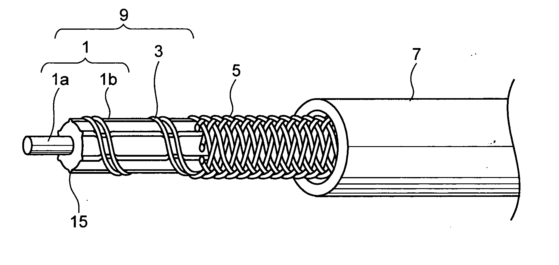
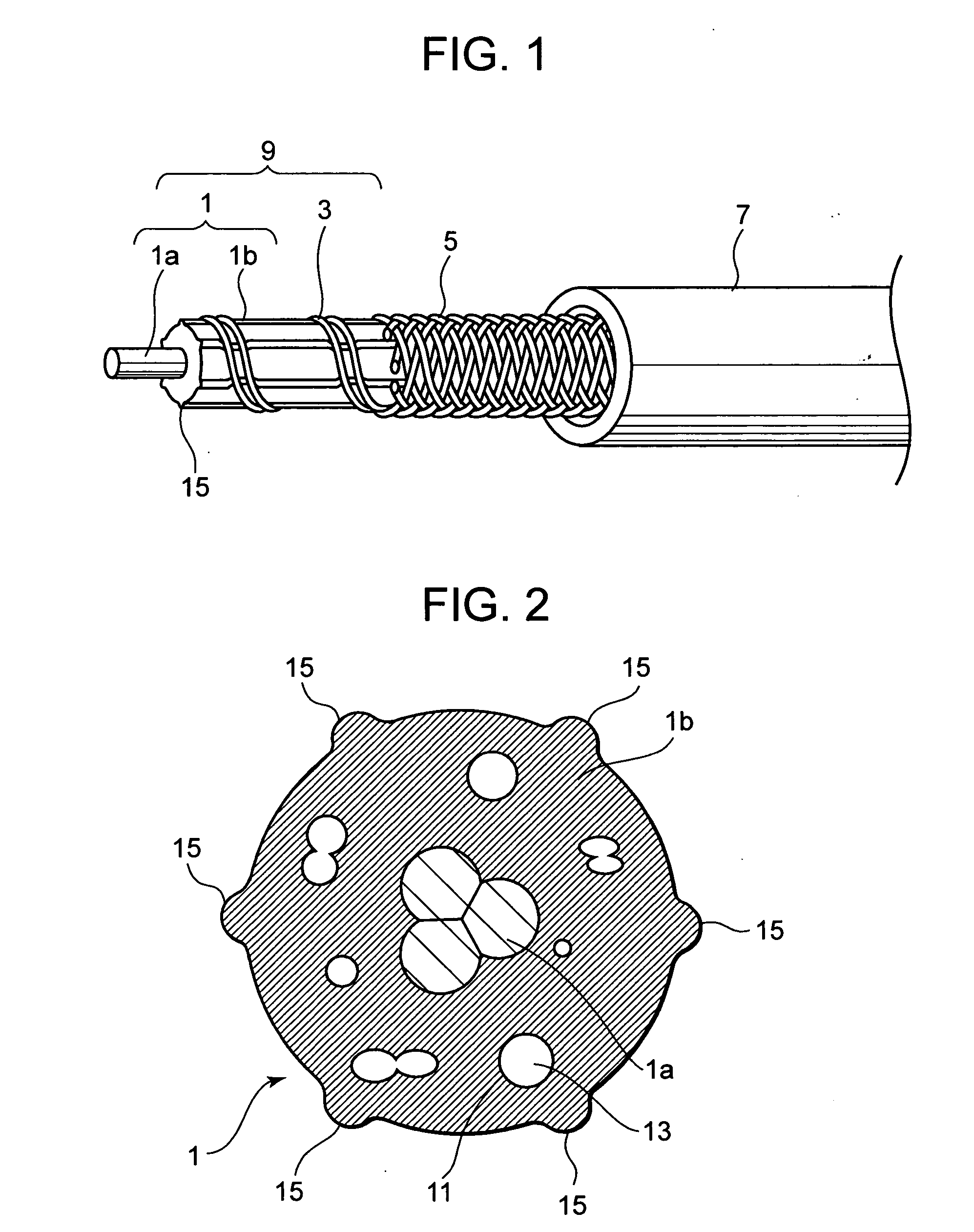
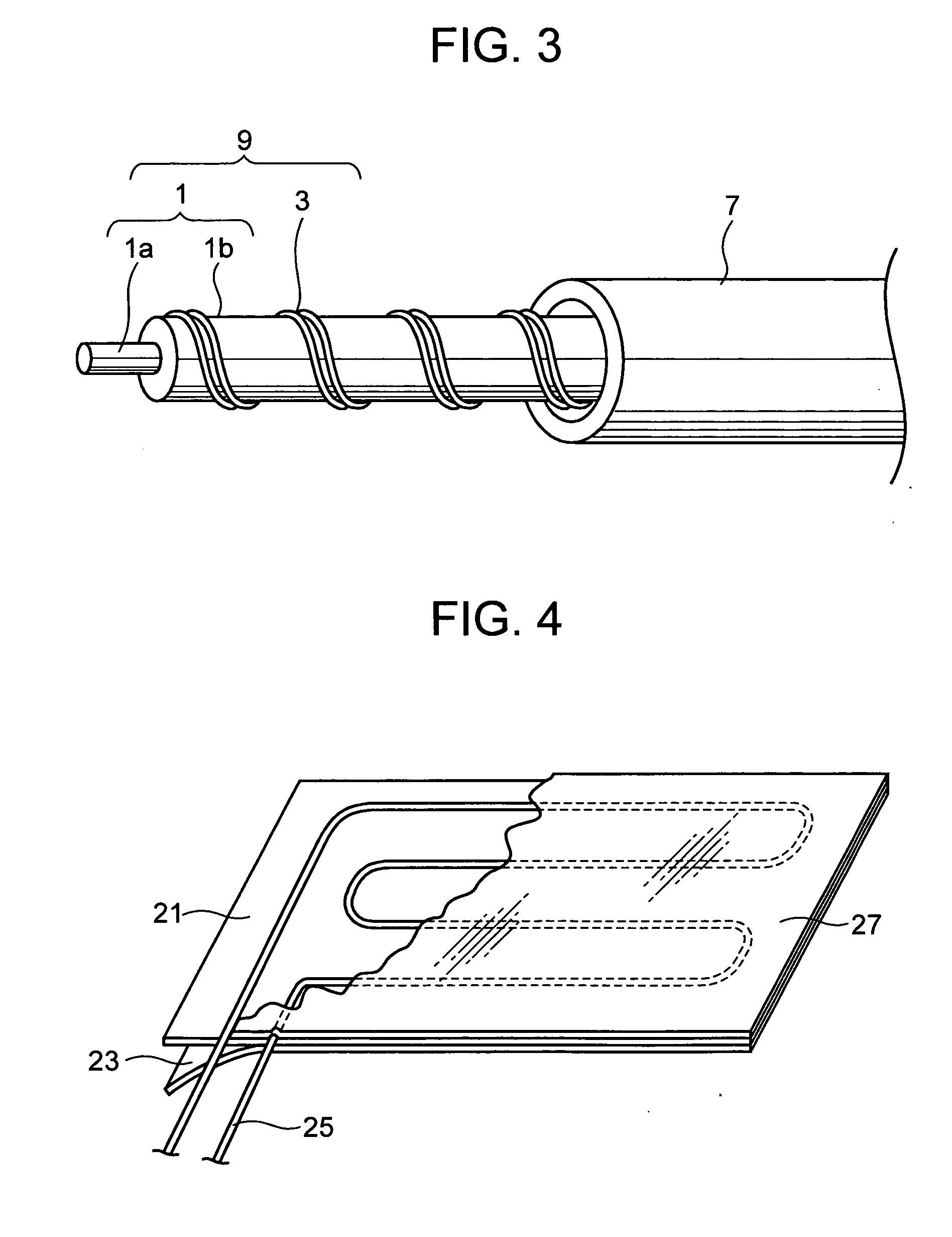
[0053] The elastic core 1 was manufactured by the following methods. First, silicone varnishing was applied to a glass code having the outer diameter of about 0.7 mm, thus the tensile resistant member 1a was provided. Thereafter, a silicone rubber, comprising a compound of 100 w / t parts (part by weight) of silicone rubber, 1 w / t part of foaming agent (AIBN) and 2 w / t parts of organic peroxide cross-linking agent kneaded on open roll, was extruded in order to cover the periphery of the tensile resistant member 1a, so that the cross-section of the silicone rubber had six radial protrusions, of which inscribed circle was 1.6 mm and of which circumscribed circle was 1.8 mm. At the same time, the silicone rubber was foamed by applying hot-air vulcanization. Thus, the foamed elastic member 1b, having isolated air holes, was formed.
[0054] Thereafter, two parallel conductors 3, respectively comprising 0.6 mm φ of eutectic solder wire (melting temperature at 183° C.) in which flux had been ...
experiment 1
ative Temperature
Experiment Method:
[0057] The code type thermal fuse assembly manufactured by the above method was inserted in a glass fiber braid tube at inner diameter of 4.0 mm and at length of about 15 cm, so that the code type thermal fuse part of the assembly may come to the center part of the tube. Thereafter, an electric current about 0.1 A was applied from 100 V AC power supply, by connecting incandescent bulb to the both terminals of the lead wires as an outer load. Then, the center part was heated from normal temperature, at temperature increase speed of 10° C. / min. Thus, when the conductor 3 was disconnected, the temperature was checked.
experiment 2
mperature After Lost of Flux
Experiment Method:
[0058] The manufactured code type thermal fuse assembly was placed in a hot-air circulation type of constant-temperature bath at temperature of 158° C., for 384 hours, whereby the deterioration due to aging by heat was prompted, and the flux was decomposed and removed by heat. Thereafter, the code type thermal fuse assembly after heat treatment was inserted in a glass fiber braid tube at inner diameter of 4.0 mm and at length of about 15 cm, so that the code type thermal fuse part of the assembly may come to the center part of the tube. Thereafter, an electric current about 0.1 A was applied from 100 V AC power supply, by connecting incandescent bulb to the both terminals of the lead wires as an outer load. Then, the center part was heated from initial temperature of 250° C., at temperature increase speed of 10° C. / min. Thus, when the conductor 3 was disconnected, the temperature was checked.
[0059] The results of Experiments 1 and 2 a...
PUM
 Abstract
Description
Claims
Application Information