Eureka AIR delivers breakthrough ideas for toughest innovation challenges, trusted by R&D personnel around the world.

Method and apparatus for deactivating an EAS device

Inactive Publication Date: 2005-11-24
YANG XIAO HUI +1
View PDF32 Cites 0 Cited by
  • Summary
  • Abstract
  • Description
  • Claims
  • Application Information

AI Technical Summary

Benefits of technology

[0010] It is an additional object of the present invention to provide an EAS deactivator having greater capability to control the attenuation of the magnetic field.
[0019] The present invention monitors the circuit via the field output of the coil, current flow, or other electromagnetic parameters and utilizes a feedback loop to adjust the coil driving input frequency to the resonant frequency of the system in that environment. Driving the coil at the system resonant frequency reduces the impedance and maximizes the field output per given energy input. Degaussing requires the attenuation of the magnetic field. In the present invention, field attenuation is accomplished by adjusting the driving frequency away from the resonant frequency of the system, usually to a higher frequency. As this occurs, the magnitude of the field output is decreased due to increased impedance in the system and circuit.

Problems solved by technology

While Easter '275 utilizes feedback to adjust the drive current, it does so in comparison to a reference signal and not the system's response, so it does not adapt to varying environments.

Method used


Image

  • Method and apparatus for deactivating an EAS device
  • Method and apparatus for deactivating an EAS device
  • Method and apparatus for deactivating an EAS device

Examples


Embodiment Construction

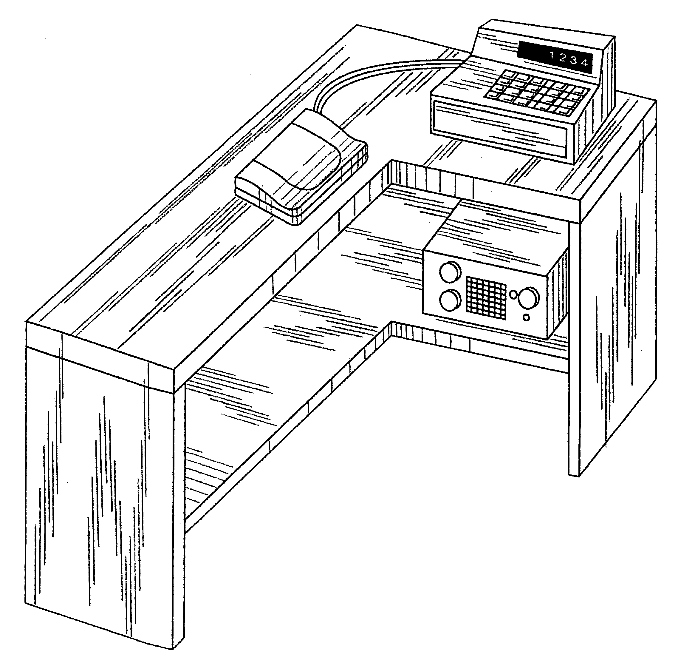
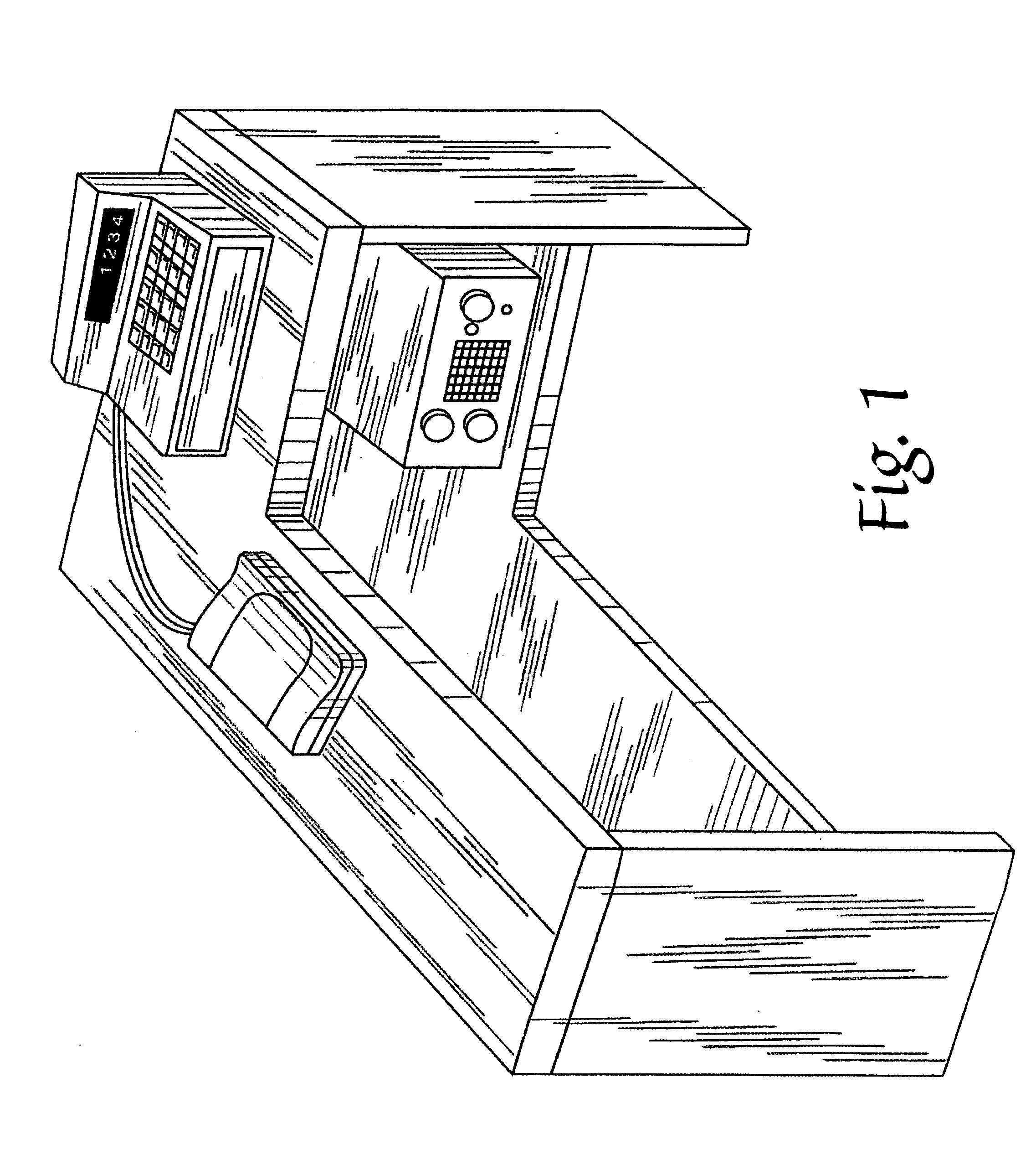
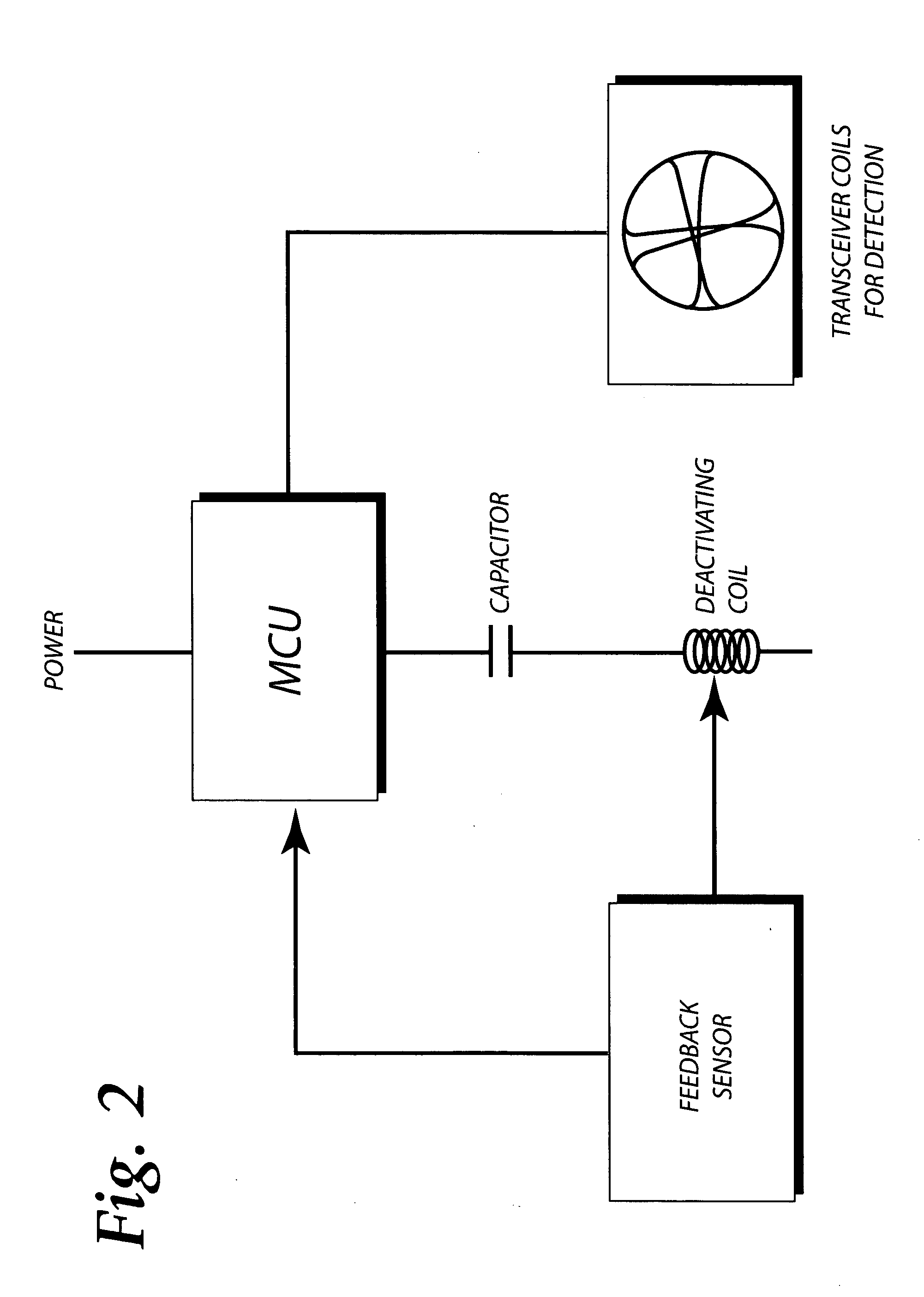
[0029] The detailed description below is for a preferred embodiment in which the microprocessor control unit operates transceiver coils and a degaussing coil with the assistance of a feedback loop. Specifically, the embodiment shown in the drawings and discussed below encloses the electrical coils in a generally flat housing and provides an alternating current to drive the circuit, while monitoring the system output. It is to be understood that a variety of other arrangements are also possible without departing from the spirit and scope of the invention.

[0030] Furthermore, before referring to the accompanying Figures, additional details regarding the preferred embodiment may be stated. The present embodiment of the invention has the control components of the circuitry separated from the field generating components. To utilize a fixed working frequency with this arrangement, the parameters of each component would have to be closely matched which would in turn require extremely deman...


PUM


Abstract

A deactivator for deactivating label-style EAS devices is claimed. The preferred embodiment, of which, employs a microprocessor unit to control two transceiver coils, and a deactivation coil in series with a capacitor. The two transceiver coils are essentially two flat figure eights arranged concentrically but rotated through some angle with respect to each other. The transceiver coils are operated alternatively, first transmitting an interrogation signal and then listening for a response. When an EAS device is detected, the microprocessor unit drives the capacitor and deactivation coil at the system's resonant frequency to generate a high amplitude magnetic field then shifts the frequency of the driving current away from the resonant frequency to attenuate the magnetic field. A field sensor or current sensor provides feedback to the microprocessor to determine the resonant frequency of the system during a frequency sweep.

Description

FIELD OF THE INVENTION [0001] This invention relates generally to a method and apparatus for deactivating electronic article surveillance labels. More specifically, this invention relates to a method and apparatus for deactivating electronic article surveillance labels having a magnetic component within them which requires degaussing in order for the electronic article surveillance label to be deactivated. BACKGROUND OF THE INVENTION [0002] An age old problem in retail sales is shoplifting or theft. A modern method of dealing with this problem is the use of electronic article surveillance tags and labels, and associated detection systems. Generally, these tags and labels have small, passive electronic circuits enclosed within them, and the tags or labels are attached to merchandise in the store. The detection system includes various types of antennas located at store exits or other areas where security is desired. Transmitting antennas broadcast a signal of a specific frequency into...

Claims


Application Information

Patent Timeline
IPC IPC(8): G08B13/24H01F13/00
CPCG08B13/2411H01F13/006G08B13/2474G08B13/2471
Inventor YANG, XIAO HUIFUSS, ARTHUR BRADLEY
Owner YANG XIAO HUI
Why Eureka
Eureka Blog
Learn More