Camera-shake compensation apparatus and position detection apparatus

a compensation apparatus and position technology, applied in the field of camera-shake compensation apparatus, can solve the problems of increasing the cost of components and the conventional camera-shake compensation apparatus, and achieve the effect of improving wiring efficiency and low cos

Inactive Publication Date: 2005-11-24
KONICA MINOLTA PHOTO IMAGING
View PDF11 Cites 34 Cited by
  • Summary
  • Abstract
  • Description
  • Claims
  • Application Information

AI Technical Summary

Benefits of technology

[0009] It is therefore an object of the present invention to provide a camera-shake compensation apparatus and a position detection apparatus which eliminate the need of installation of electric wiring in at least one of a fixed part and a moving part to thereby improve efficiency in wiring, as well as maintain low cost.
[0012] The foregoing structure allows satisfactory detection of the position of the moving part in the predetermined plane. Also, there is no need of installing electric wiring in a part in which the magnet is provided. Further, the magnet is less expensive than a semiconductor component or the like, the position detection apparatus can be implemented at a lower cost.
[0014] There is no need of installing electric wiring in the moving part. Accordingly, a resistance to movement of the moving part can be reduced.
[0016] It is possible to detect positions on two axes perpendicular to each other by using a single magnet, to thereby allow for minimization of the size of the position detection apparatus.

Problems solved by technology

However, the conventional camera-shake compensation apparatus described above requires installation of electric wiring in each of the light emitting device and the light receiving device.
As such, the conventional camera-shake compensation apparatus suffers from the need of installation of wiring for position detection in both the fixed part and the moving part during assembling the camera-shake compensation apparatus.
Also, to use the infrared LED, the PSD or the other component, which is relatively expensive, would result in increased cost for components.

Method used


Image

  • Camera-shake compensation apparatus and position detection apparatus
  • Camera-shake compensation apparatus and position detection apparatus
  • Camera-shake compensation apparatus and position detection apparatus

Examples


Embodiment Construction

[0027] Below, a preferred embodiment of the present invention will be described in detail with reference to accompanying drawings. In the drawings, an X, Y, Z-three-dimensional Cartesian coordinate system is used in common.

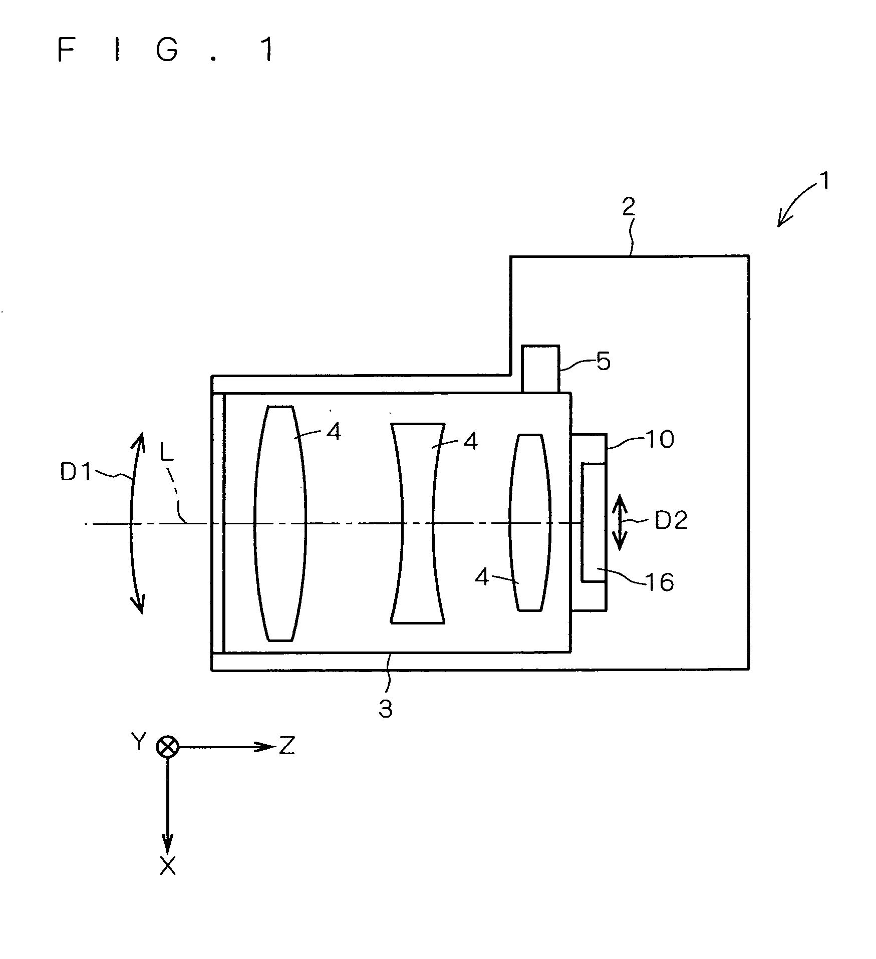
[0028]FIG. 1 illustrates an image capture apparatus 1 such as a digital camera which is capable of compensating for camera shake. The image capture apparatus 1 includes a camera body 2, a lens barrel 3 in which a plurality of lenses 4 are mounted, a camera-shake compensation apparatus 10 attached to an end face of the lens barrel 3, and a gyro sensor 5 secured to a side face of the lens barrel 3.

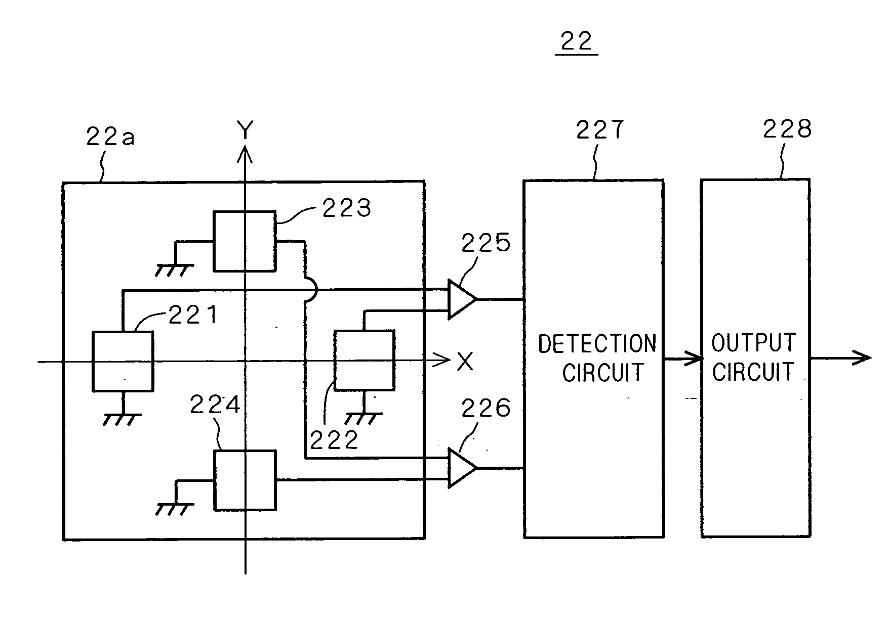
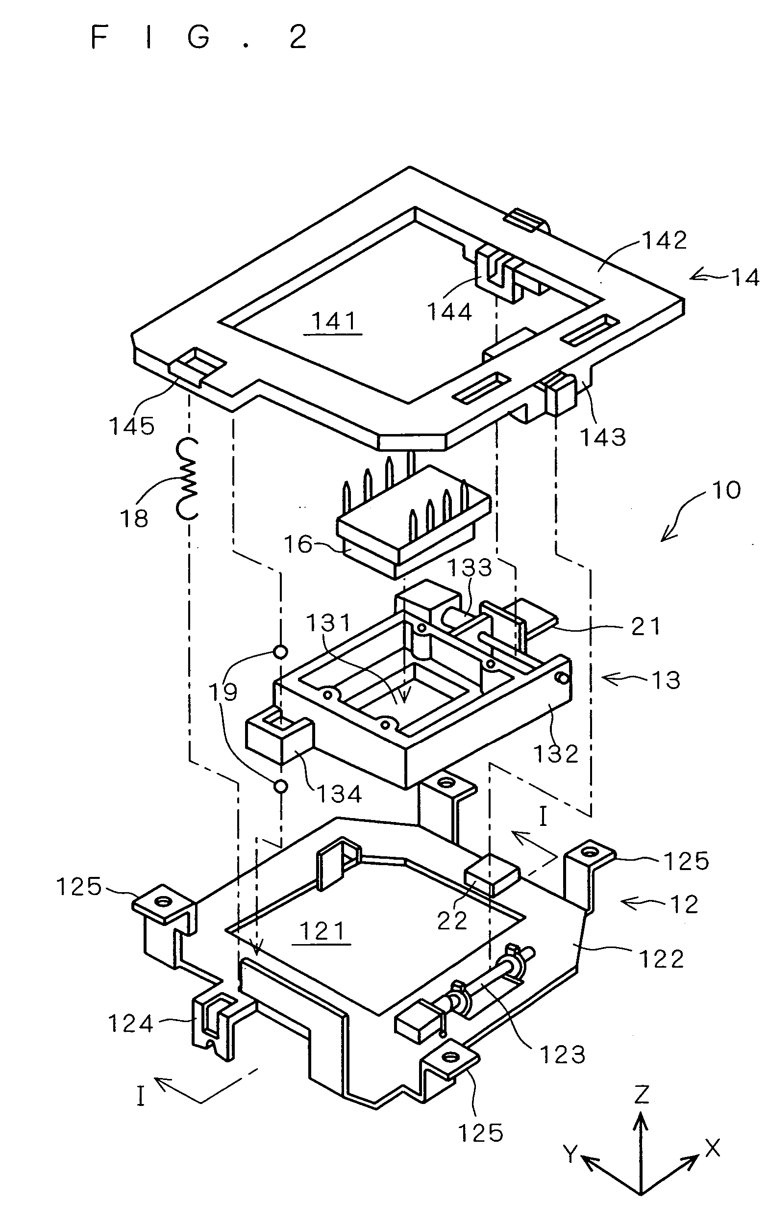
[0029] In the camera-shake compensation apparatus 10, an imaging device 16 such as a CCD is provided. The camera-shake compensation apparatus 10 moves the imaging device 16 in an X-Y plane perpendicular to an optical axis L in response to shake of the image capture apparatus 1 which is detected by the gyro sensor 5, to compensate for camera shake. For example, consider a...


PUM


Abstract

A base plate, a first slider and a second slider are fit in one another to produce one assemblage. The first slider is caused to move relative to the base plate along an X axis by a first actuator. The second slider moves in unison with the first slider, and also is caused to solely move along a Y axis by a second actuator. A magnetic sensor unit is provided in the base plate, and a magnet support is provided in the second slider so as to face the magnetic sensor unit. A magnet is disposed on a lower face of the magnet support. The magnetic sensor unit and the magnet form a position detection mechanism, and the second slider in which the magnet is disposed requires no electric wiring.

Description

[0001] This application is based on application No. 2004-147315 filed in Japan, the contents of which are hereby incorporated by reference. BACKGROUND OF THE INVENTION [0002] 1. Field of the Invention [0003] The present invention relates to a camera-shake compensation apparatus of an image capture apparatus and a position detection apparatus applicable to the camera-shake compensation apparatus. [0004] 2. Description of the Background Art [0005] As an image capture apparatus such as a digital camera, well known is of a type which cancels image blur on a receiving face by causing an imaging device to move responsive to possible camera shake which is likely to occur during photographing (as taught in Japanese Patent Application Laid-Open No. 2003-110929, for example, which will be hereinafter referred to as “JP 2003-110929”). [0006] In a camera-shake compensation apparatus taught in JP 2003-110929, assuming that the apparatus is roughly divided into a moving side at which a moving par...

Claims


Application Information

Patent Timeline
Patent Type & Authority Applications(United States)
IPC IPC(8): H04N5/225G03B5/00H04N5/228H04N5/232
CPCH04N5/2253H04N5/23287H04N5/23248H04N23/54H04N23/68H04N23/687
Inventor KOSAKA, AKIRAMASUDA, SATOSHIHARA, YOSHIHIROISHITO, FUMIAKI
Owner KONICA MINOLTA PHOTO IMAGING
Why Eureka
Try Eureka