Projection lens system and projector

a projector and lens system technology, applied in the field of projector projection lens system, can solve the problems of difficult to reduce distortion, slim rear projector, and increased length of the first lens group positioned on the screen side, so as to achieve slim overall construction, improve the effect of reducing distortion and reducing distortion

Inactive Publication Date: 2005-11-24
NITTO OPTICAL CO LTD
View PDF1 Cites 8 Cited by
  • Summary
  • Abstract
  • Description
  • Claims
  • Application Information

AI Technical Summary

Benefits of technology

[0010] It is preferable for the first lens group to have an overall negative refractive power, for a second lens group with positive refractive power to be disposed on the light modulator side of the first lens group, and for a cemented lens to be disposed on a screen side of the second lens group. Applying such an arrangement, it is possible to provide a projection lens system that is an overall retrofocus-type lens system, is highly symmetrical in that cemented lenses are disposed on the light modulator side of the first lens group and the screen side of the second lens group, respectively, and where the part of the first lens group bent toward the front is slim. It is possible to provide a projection lens system that has a long back focus and is telecentric on the incident side, with the overall system being thin and various kinds of aberration being favorably corrected. In addition, by including at least three cemented lenses, that is at least two sets of cemented lens in addition to the cemented lens positioned closest to the screen in the second lens group that has positive refractive power, it is possible to provide a bright projection lens system where the chromatic difference of magnification is favorably corrected and a peripheral brightness ratio of 75% or higher is achieved in spite of the lens system being wide-angle.
[0011] Accordingly, a projector including a projection lens system according to the present invention and a light modulator is slim, compact, and can display images on a large screen, and is therefore suited to a rear-projection-type image display apparatus.
[0012] As explained, by disposing a means for bending an optical path, such as a mirror or a prism, between the lenses of the first lens group (the closest group to the screen in a projection lens system) and in particular, by disposing the means on a screen side of a cemented lens (balsam lens), it is possible to reduce the number of lenses in front of (i.e., on the screen side) of the bend so that the lens system can be made slim, even if a cemented lens is used in the first lens group. Accordingly, it is possible to provide a projection lens system that has a slim overall construction and in which aberration is favorably corrected.

Problems solved by technology

However, retrofocus-type lens systems are normally highly asymmetric, which makes it difficult to reduce distortion.
However, cemented lenses are combinations of a positive lens and a negative lens, and so tend to be thick, which increases the length of the first lens group positioned on the screen side.
Accordingly, such lens system is not suited to being enclosed inside a compact, slim rear projector.

Method used


Image

  • Projection lens system and projector
  • Projection lens system and projector
  • Projection lens system and projector

Examples


Embodiment Construction

)

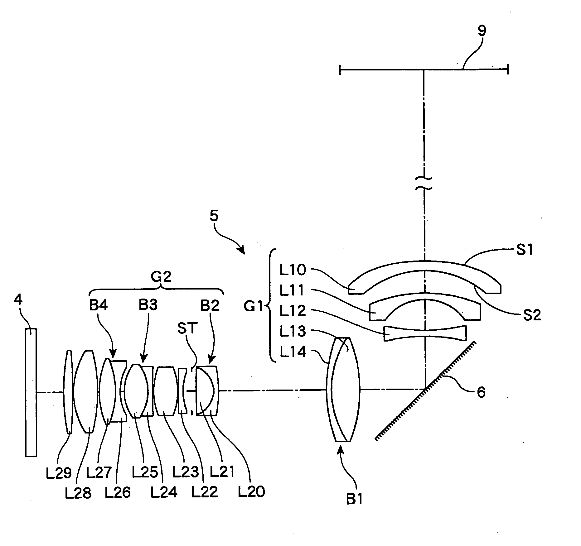
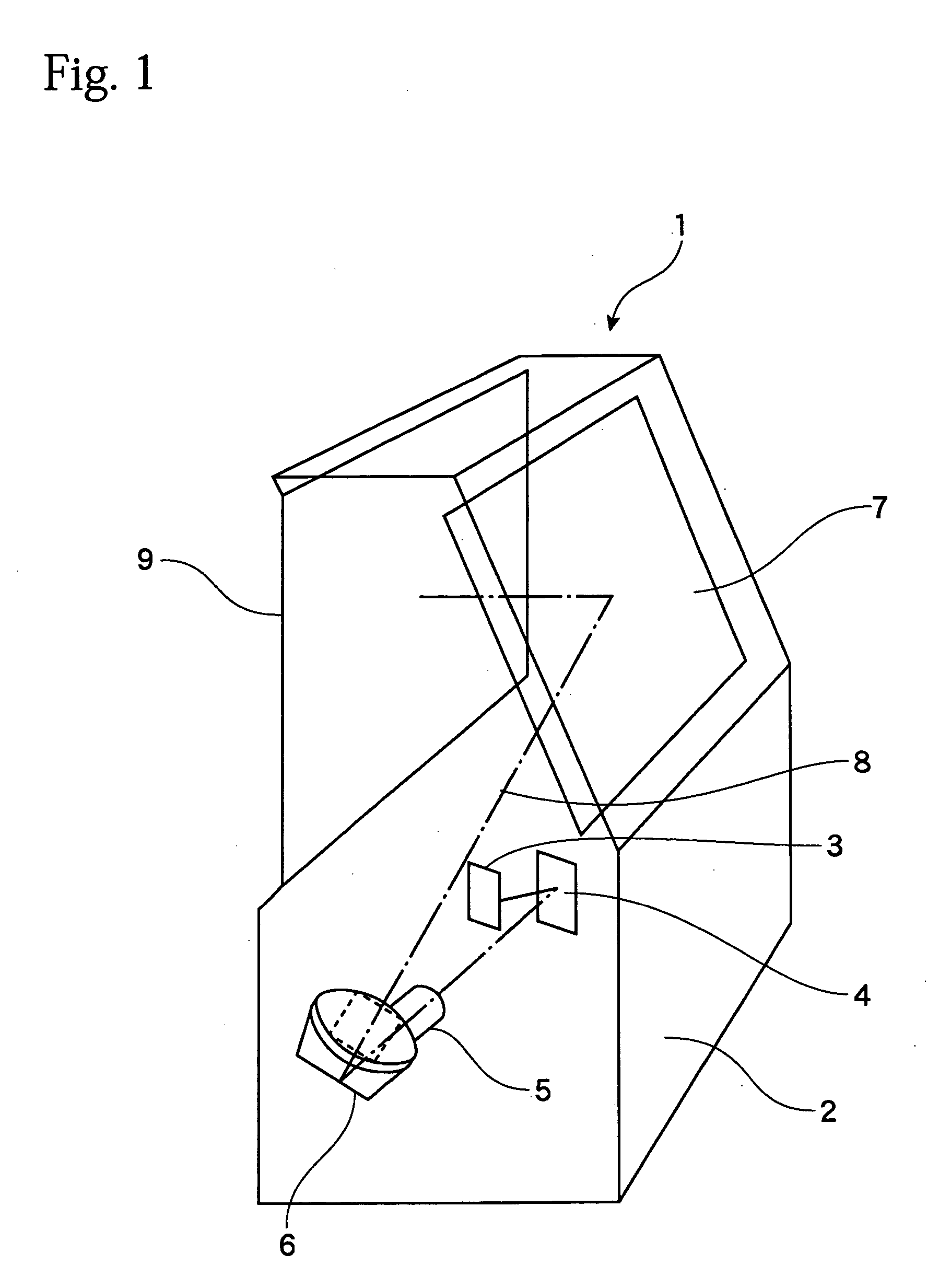
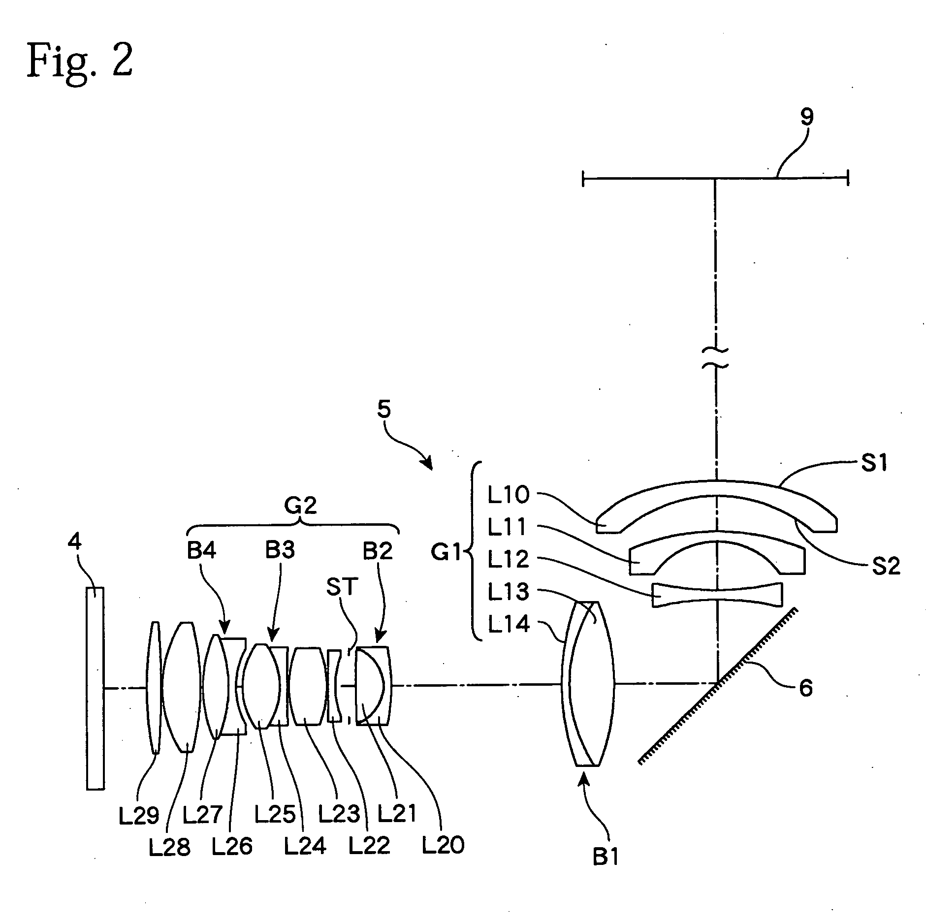
[0019]FIG. 1 shows the construction of a rear projector 1 equipped with a projection lens system according to the present invention. The rear projector 1 includes, inside a housing 2, a light source 3, a light modulator (light valve) 4 that modulates light from the light source 3 according to an image signal to form an image, a projection lens system 5 that projects projection light 8 from the light valve 4 onto a screen 9 from the rear surface side, and a mirror 7 that reflects and guides the projection light 8 to the screen 9. A liquid crystal panel is often used as the light valve 4, but it is also possible to use a DMD panel composed of micro-mirror elements. When a DMD panel or an LCOS (reflective liquid crystal) panel is used, the light valve 4 is reflective, and accordingly the light source 3 is disposed on the same side of the light valve 4 as the projection lens system 5. It is therefore necessary to use a lens system with a long back focus as the projection lens system 5....


PUM


Abstract

A projection lens system of the present invention projects projection light from a light modulator onto a screen and includes a first lens group disposed closest to the screen, the first lens group including a first meniscus lens with negative refractive power that is positioned closest to the screen and is convex on a screen side, a cemented lens that is positioned on a light modulator side, and a means for bending an optical path between the first meniscus lens and the cemented lens. The means for bending the optical path is disposed between the negative meniscus lens and the cemented lens of the first lens group. Since the cemented lens of the first lens group is disposed in line with the lenses in the second lens group, the lens system of this invention is produced with a slim overall construction even if the cemented lens is in the first lens group.

Description

BACKGROUND OF THE INVENTION [0001] 1. Field of the Invention [0002] The present invention relates to a projection lens system of a projector that enlarges and projects an image displayed on a light valve, such as a liquid crystal panel or a DMD, onto a screen. [0003] 2. Description of the Related Art [0004] Rear-projection-type devices are known as image display apparatuses with large screen sizes and slim bodies. It is disclosed in Japanese Laid-Open Patent Publication No. 2001-42211 and in Japanese Laid-Open Patent Publication No. H09-218379 that the height and depth of a projector can be reduced by disposing a prism for bending the optical path at an intermediate position behind a closest lens group to the screen in a lens system so that the optical path is bent by 90° or thereabouts. [0005] When a liquid crystal panel is used as the light valve (light modulator), and in particular when an LCOS (Liquid Crystal on Silicon) panel (i.e., a reflective liquid crystal panel) or a DMD (...

Claims


Application Information

Patent Timeline
Patent Type & Authority Applications(United States)
IPC IPC(8): G02B13/16G02B9/58G02B13/04G02B13/18G02B15/14G02B15/177G02B17/08G03B21/00G03B21/14
CPCG02B13/16G02B13/04
Inventor KOBAYASHI, KIWAMU
Owner NITTO OPTICAL CO LTD
Why Eureka
Try Eureka