
Unsafe voltage shutoff control

a voltage shutoff and unsafe technology, applied in the direction of emergency protective arrangements for limiting excess voltage/current, electrical equipment responsive to excess voltage, etc., can solve the problems of sustained ac over-voltage, surges and other transients of high current or voltage, permanent damage to electrical equipment connected to the power line, etc., to avoid nuisance cycling

Active Publication Date: 2005-11-24
CORE BRANDS
View PDF78 Cites 48 Cited by
  • Summary
  • Abstract
  • Description
  • Claims
  • Application Information

AI Technical Summary

Benefits of technology

[0015] Further, in or to avoid nuisance cycling of the protection circuit when the over-voltage condi

Problems solved by technology

Electrical power lines are often subject to surges and other transients of high current or voltage caused by various events, such as lightning, switching on or off significant electrical loads, or even occasional short circuits.
Such surges or transients can cause permanent damage to electrical equipment connected to the power line, particularly equipment in which electronic devices are responsible for the consumption and use of the power.
For example, poor voltage regulation by the electrical utility provider, improper wiring of the facility, use of standby generators, or incorrect or defective bonding of neutral and ground line connections can all lead to sustained AC over-voltage.
Under such sustained over-voltage conditions, conventional TVSS devices, which use voltage-limiting components (e.g., metal oxide varistors or “MOV”s) to limit transients of short duration, will either be ineffective (if their limiting, or “let-through,” voltage is more than the peak value of the power line voltage) or simply burn out, since MOV voltage limiters overheat in a very short time when absorbing the excessive power associated with the over-voltage.
It is another objective to also disconnect the load and surge protector components under more sustained over voltage conditions, which would result in damage to the MOV, and / or require a thermal fuse coupled to the MOV.

Method used


Image

  • Unsafe voltage shutoff control
  • Unsafe voltage shutoff control
  • Unsafe voltage shutoff control

Examples


Embodiment Construction

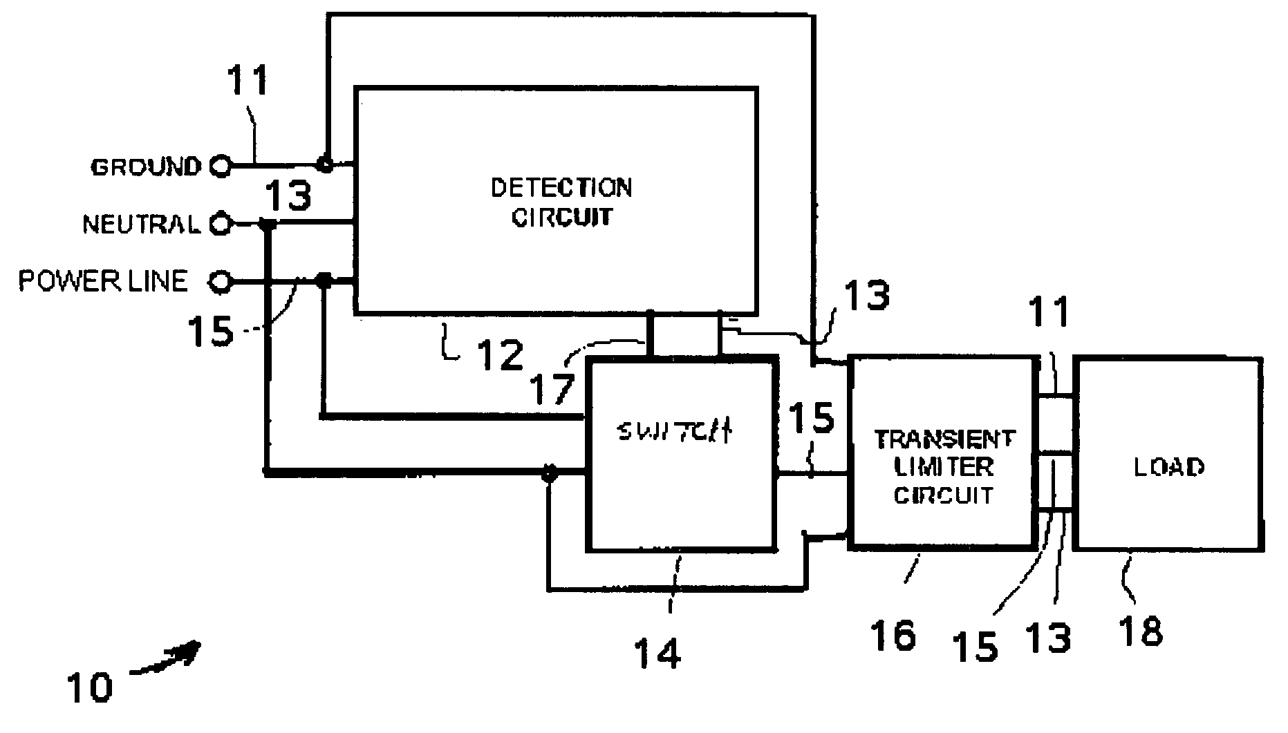
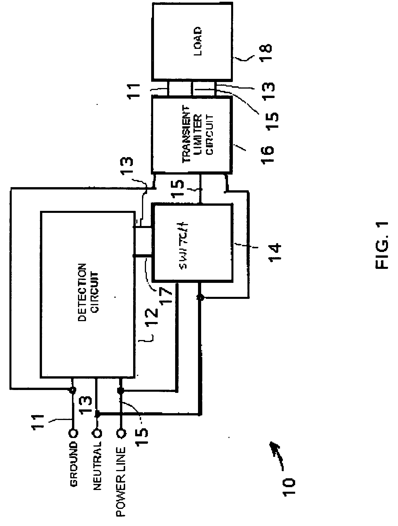
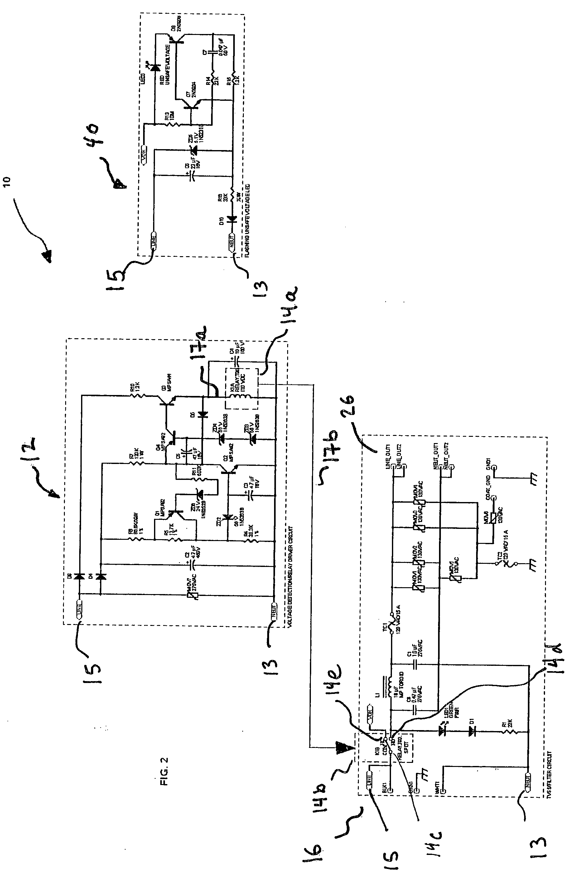
[0021] Referring to FIG. 1, an unsafe voltage protection circuit 10 for protecting a load 18 against sustained under-voltage or over-voltage conditions includes a voltage detection circuit 12, a switch 14 and a transient limiter circuit 16, all interconnected substantially as shown (and discussed in more detail below). The ground 11, neutral 13 and power 15 lines connect to the voltage detection circuit 12, switch 14 and transient limiter circuit 16. The voltage detection circuit 12 is, in the broadest embodiments, capable of monitoring the inter-terminal voltages between any two of the combination of the ground 11, neutral 13 and power 15 lines, but will be described with respect to the protection for unsafe voltage conditions detected by the inter-terminal voltage between ground and line.

[0022] In one embodiment, whenever the voltage between the line terminal and the neutral terminal exceeds a predetermined maximum voltage, the voltage detection circuit 12, via control 17, instru...


PUM


Abstract

A circuit and device protects connected equipment from a broad range of unsafe conditions of over-voltage and under-voltage by disconnecting the line voltage before surge protection components, generally MOVs, are damaged from sustained surges. However, nuisance tripping of the protective circuit is avoiding by discriminating surges that are properly handled by the MOVs and components in the load or protective device. Further, the devise are protected from sustained high voltage line conditions, which would ordinarily result in repeated cycling between the on and off states as the line voltages fluctuates slightly at or about the trip threshold, as the circuit has a deliberate hysteresis such that the turn on voltage is about 10 to 20 V lower than the shut off threshold.

Description

CROSS REFERENCE TO RELATED APPLICATIONS [0001] None BACKGROUND OF INVENTION [0002] The present invention relates to transient voltage surge suppressors (TVSS) for protecting electrical equipment connected to alternating current (AC) electrical power lines, and in particular, to TVSS circuits for protecting electrical loads from sustained excessive AC voltages. [0003] Electrical power lines are often subject to surges and other transients of high current or voltage caused by various events, such as lightning, switching on or off significant electrical loads, or even occasional short circuits. Such surges or transients can cause permanent damage to electrical equipment connected to the power line, particularly equipment in which electronic devices are responsible for the consumption and use of the power. Transient voltage surge suppressors have long been used to detect and attempt to divert such surges and transients before they reach the devices connected to the power line. The TVSS ...

Claims


Application Information

Patent Timeline
IPC IPC(8): H02H3/06H02H3/20H02H9/04
CPCH02H3/06H02H9/04H02H3/207
Inventor HOOPES, MICHAEL L.
Owner CORE BRANDS
Learn More