Lighting device, liquid crystal display device, and electronic apparatus
a liquid crystal display and light source technology, applied in the direction of static indicating devices, lighting and heating devices, instruments, etc., can solve the problems of liquid crystal display devices having a usability problem, and it is difficult to read the display from a direction deviating from the viewing angl
- Summary
- Abstract
- Description
- Claims
- Application Information
AI Technical Summary
Benefits of technology
Problems solved by technology
Method used
Image
Examples
first embodiment
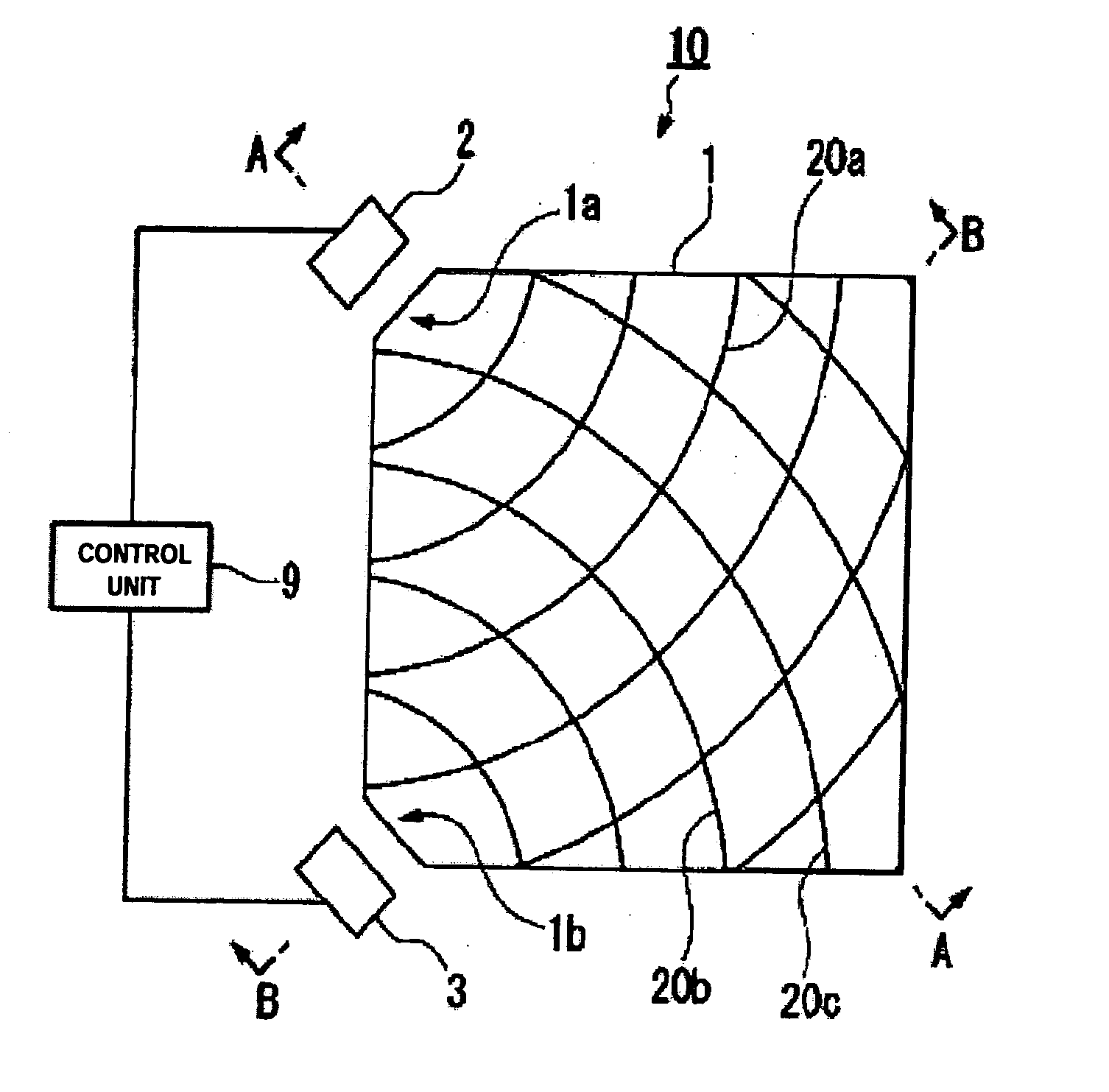
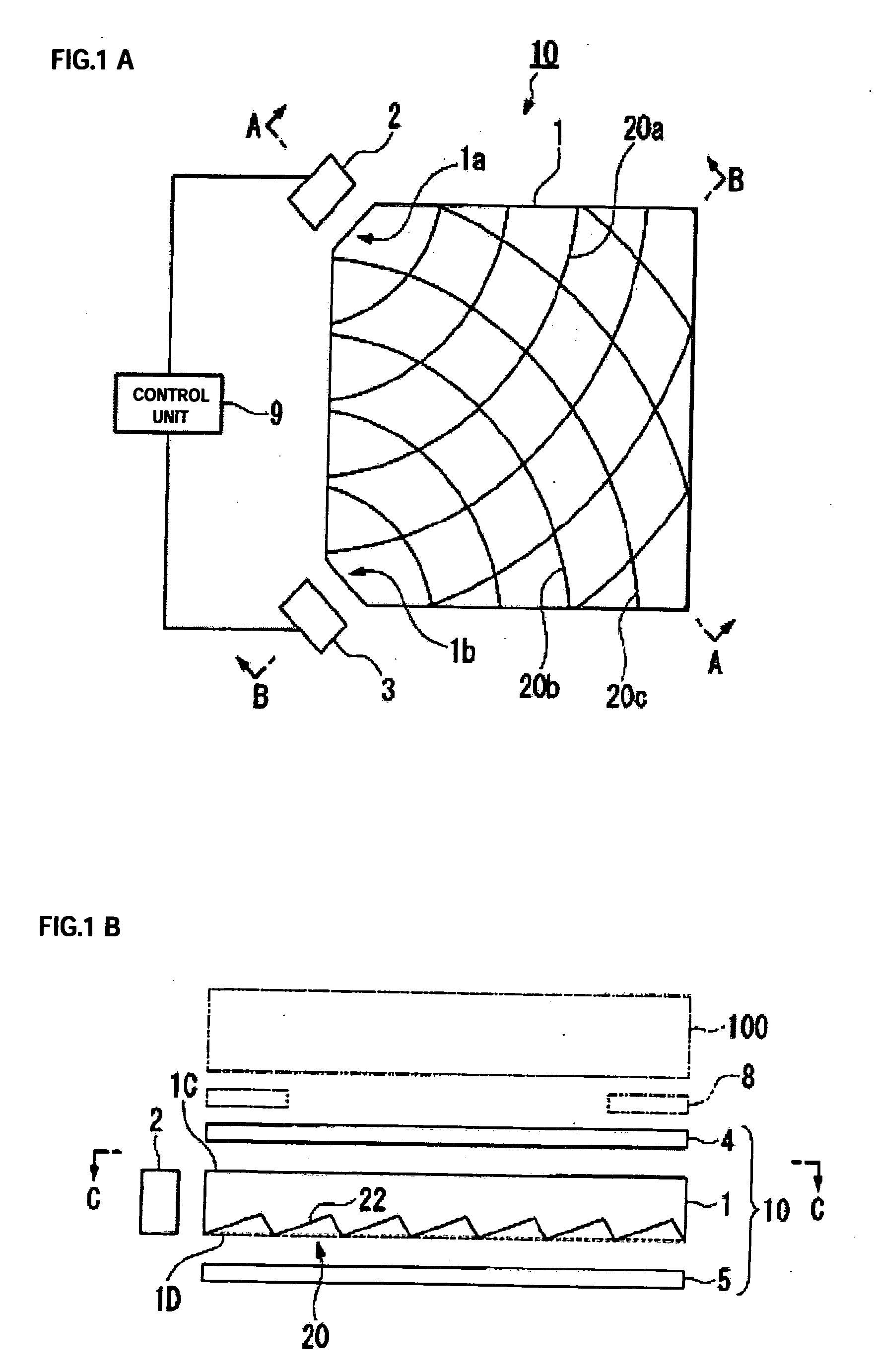
[0042]FIGS. 1A and 1B are explanatory diagrams illustrating a lighting device according to a first embodiment of the invention. The lighting device 10 according to the embodiment mainly includes an optical waveguide 1 having a rectangular flat plate shape, a first light source 2 and a second light source 3 both of which are disposed in opposite to corners of the optical waveguide 1, a reflective sheet 5 disposed on a rear surface of the optical waveguide 1, and a diffuser sheet 4 disposed on a front surface of the optical waveguide 1.
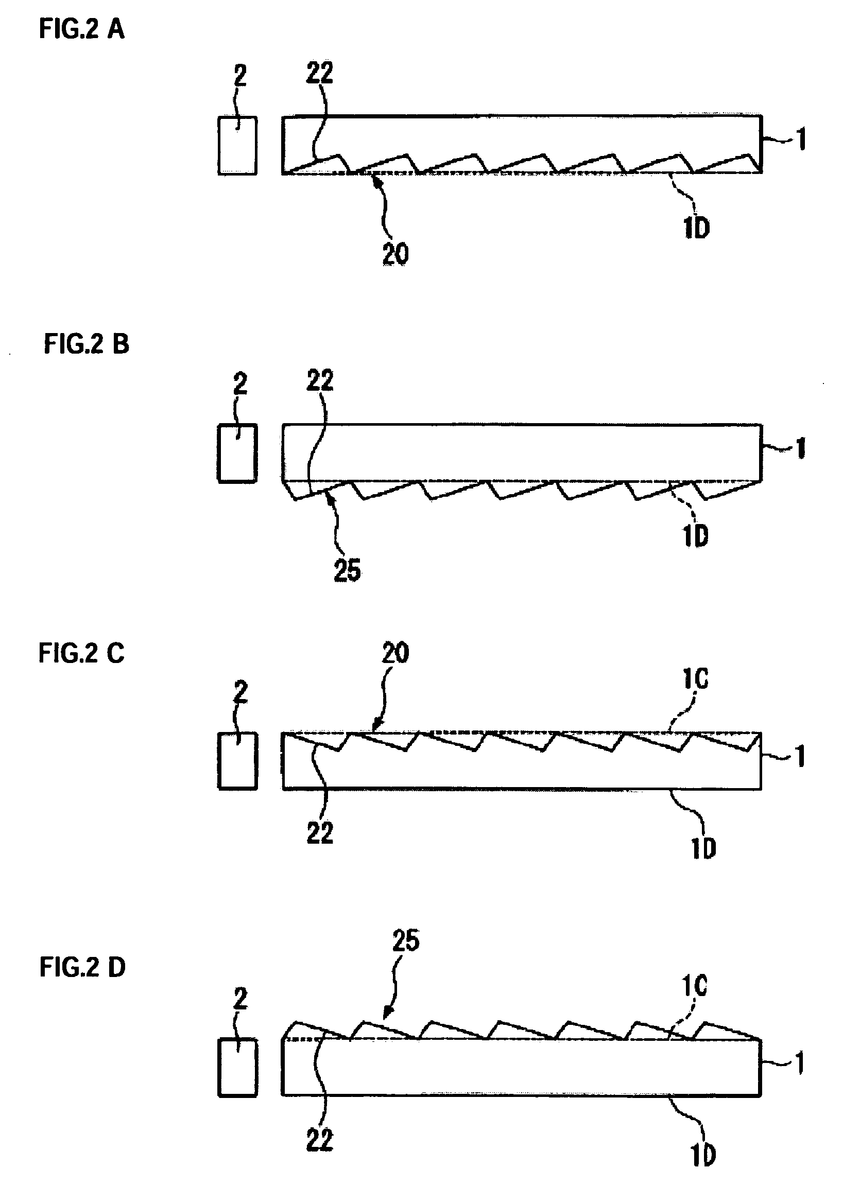
[0043]FIG. 1A is a plan view of the lighting device according to a first embodiment of the invention, which is a cross-sectional view of the lighting device taken along line C-C of FIG. 1B. The lighting device 10 of the embodiment includes the optical waveguide 1 of a rectangular flat panel shape. The optical waveguide 1 is formed about 0.6 mm in thickness using a light-transmissive material such as an acrylic resin. Further, longitudinal corners 1A an...
second embodiment
[0061]FIG. 5 is an explanatory diagram illustrating a lighting device according to a second embodiment of the invention. The lighting device of the second embodiment is different from that of the first embodiment in which the diffuser sheet is disposed on the front surface 1C of the optical waveguide 1, in that a prism sheet 6 having indentations and protrusions is disposed at a side opposite to the front surface 1C of the optical waveguide 1. Furthermore, the shape of grooves formed in the optical waveguide 1 is different from those of the first embodiment. Moreover, the same reference numerals indicate the same components as those of the first embodiment, and detailed description thereof will be omitted.
[0062] In the second embodiment, the prism sheet 6 is disposed on the front surface 1C of the optical waveguide 1, as shown in FIG. 5. The prism sheet 6 includes a plurality of prisms 7 having a tripod pillar shape or a square pillar shape, which are formed by using a light-transm...
PUM
 Abstract
Description
Claims
Application Information
 - R&D
- Intellectual Property
- Life Sciences
- Materials
- Tech Scout
- Unparalleled Data Quality
- Higher Quality Content
- 60% Fewer Hallucinations
Browse by: Latest US Patents, China's latest patents, Technical Efficacy Thesaurus, Application Domain, Technology Topic, Popular Technical Reports.
© 2025 PatSnap. All rights reserved.Legal|Privacy policy|Modern Slavery Act Transparency Statement|Sitemap|About US| Contact US: help@patsnap.com


