
Image processing apparatus and method, and recording medium and program used therewith

a technology of image processing and image processing, which is applied in the field of image processing apparatuses and methods, and recording media and programs, can solve the problems of significant visual deterioration, method has bad detection accuracy in pixels, and generated images have significant visual deterioration, so as to improve the accuracy of motion vector detection by the gradient method

Inactive Publication Date: 2005-11-24
SONY CORP
View PDF7 Cites 33 Cited by
  • Summary
  • Abstract
  • Description
  • Claims
  • Application Information

AI Technical Summary

Benefits of technology

[0022] According to the present invention, the accuracy of motion vector detection by the gradient method can be improved. In addition, according to the present invention, visual deterioration in a generated image, in particular, considerable visual deterioration in the vicinity of a boundary having movement can be suppressed.

Problems solved by technology

Although the gradient method has a feature capable of detecting a movement below pixel size by performing a simplified arithmetic operation, the method has bad accuracy for detection in units of pixels.
In this case, it is common that improbable motion vectors are detected, thus causing a problem of significant deterioration in accuracy of motion vector detection.
In addition, when the detected improbable motion vectors are used to perform frame frequency conversion, a resultant generated image has significant visual deterioration such as occurrence of noise or discontinuity in a boundary between objects in the image.

Method used


Image

  • Image processing apparatus and method, and recording medium and program used therewith
  • Image processing apparatus and method, and recording medium and program used therewith
  • Image processing apparatus and method, and recording medium and program used therewith

Examples


Embodiment Construction

[0089] Embodiments of the present invention are described below with reference to the accompanying drawings.

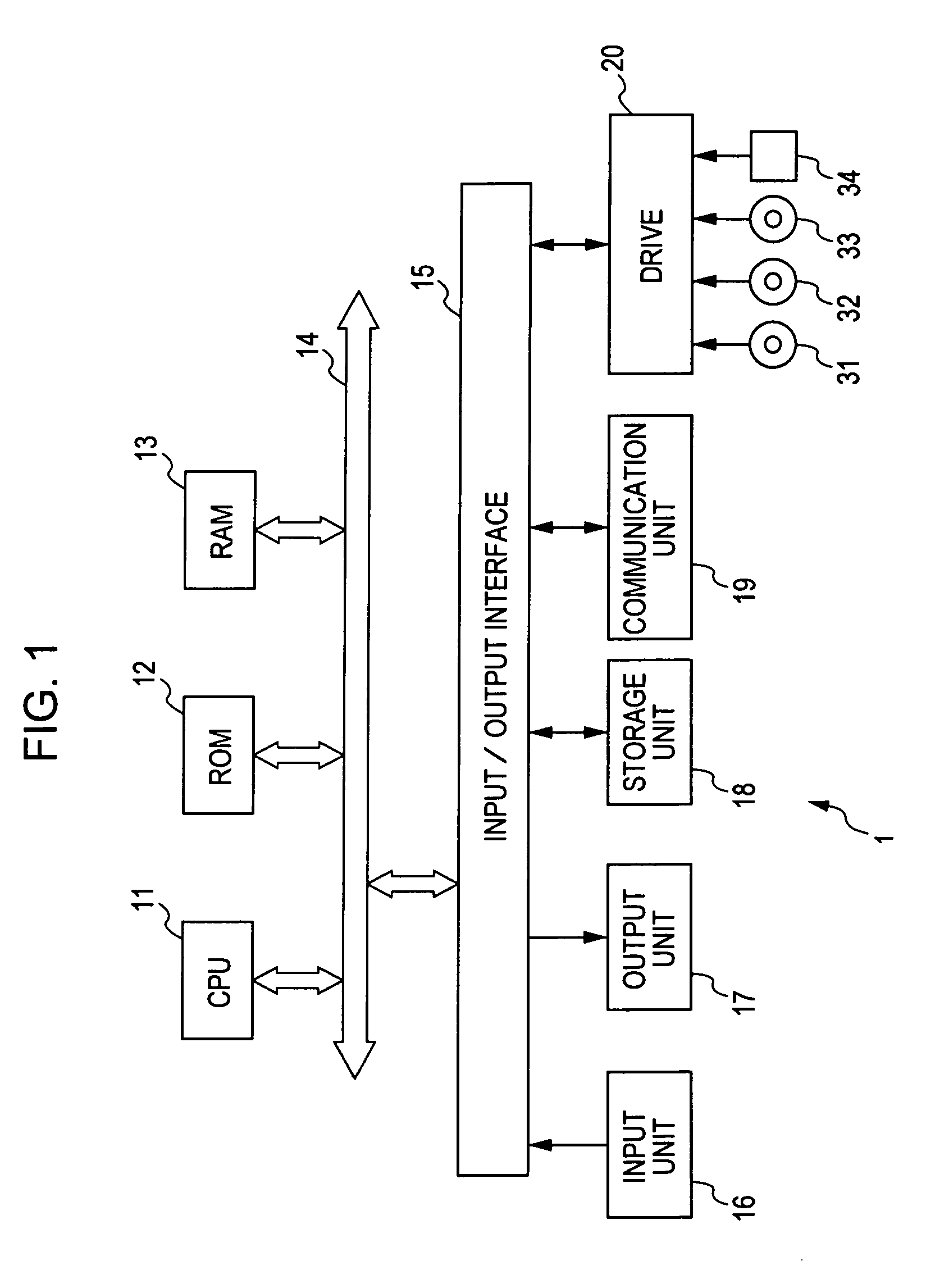
[0090]FIG. 1 shows an example of the configuration of a signal processing apparatus 1 to which the present invention is applied. The signal processing apparatus 1 is formed by, for example, a personal computer or the like. In FIG. 1, a central processing unit (CPU) 11 executes various types of processing in accordance with programs stored in a read-only memory (ROM) 12 or a storage unit 18. A random access memory (RAM) 13 stores a program to be executed by the CPU 11 and data, if needed. The CPU 11, the ROM 12, and the RAM 13 are connected to one another by a bus 14.

[0091] The CPU 11 connects to an input / output interface 15 through the bus 14. The input / output interface 15 connects to an input unit 16 including a keyboard, a mouse, and a microphone, and to an output unit 17 including a display and a speaker. The CPU 11 executes various types of processing in response to inst...


PUM


Abstract

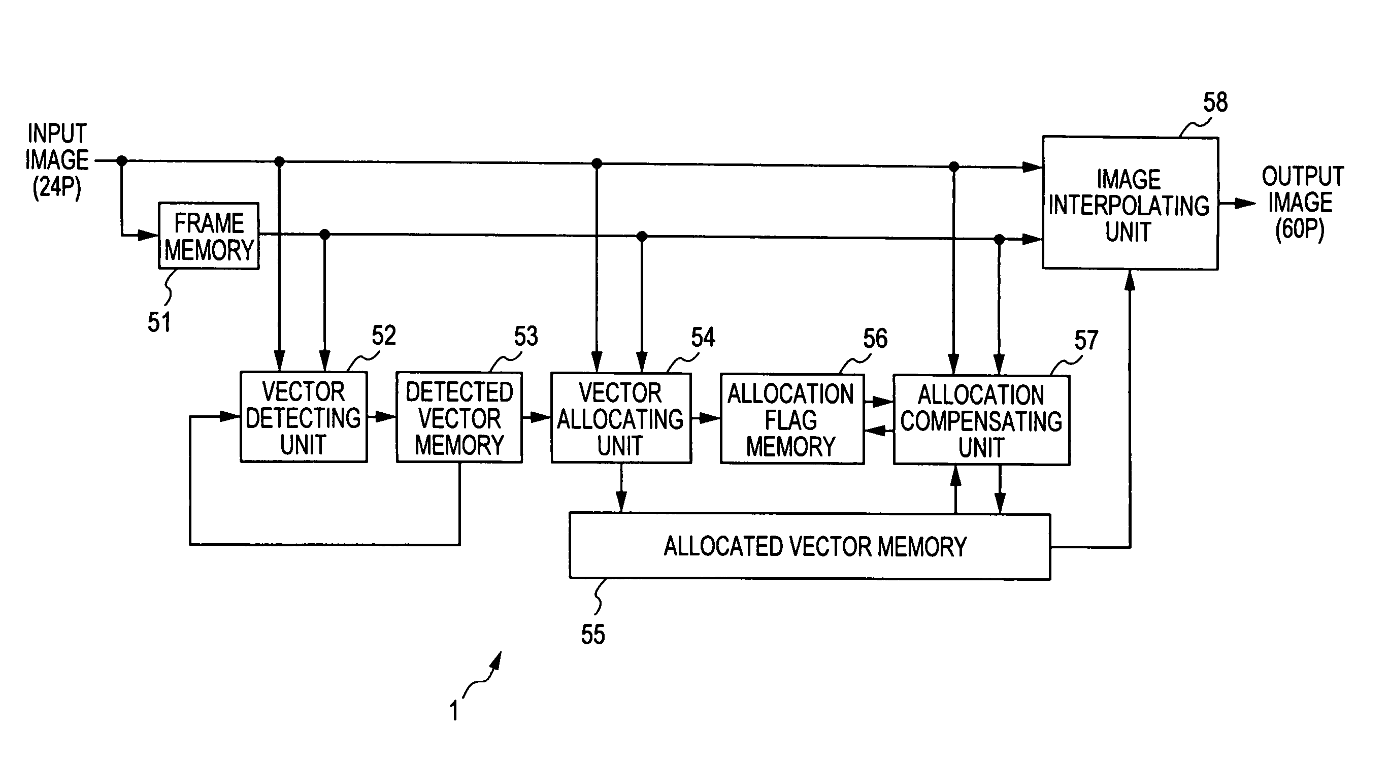
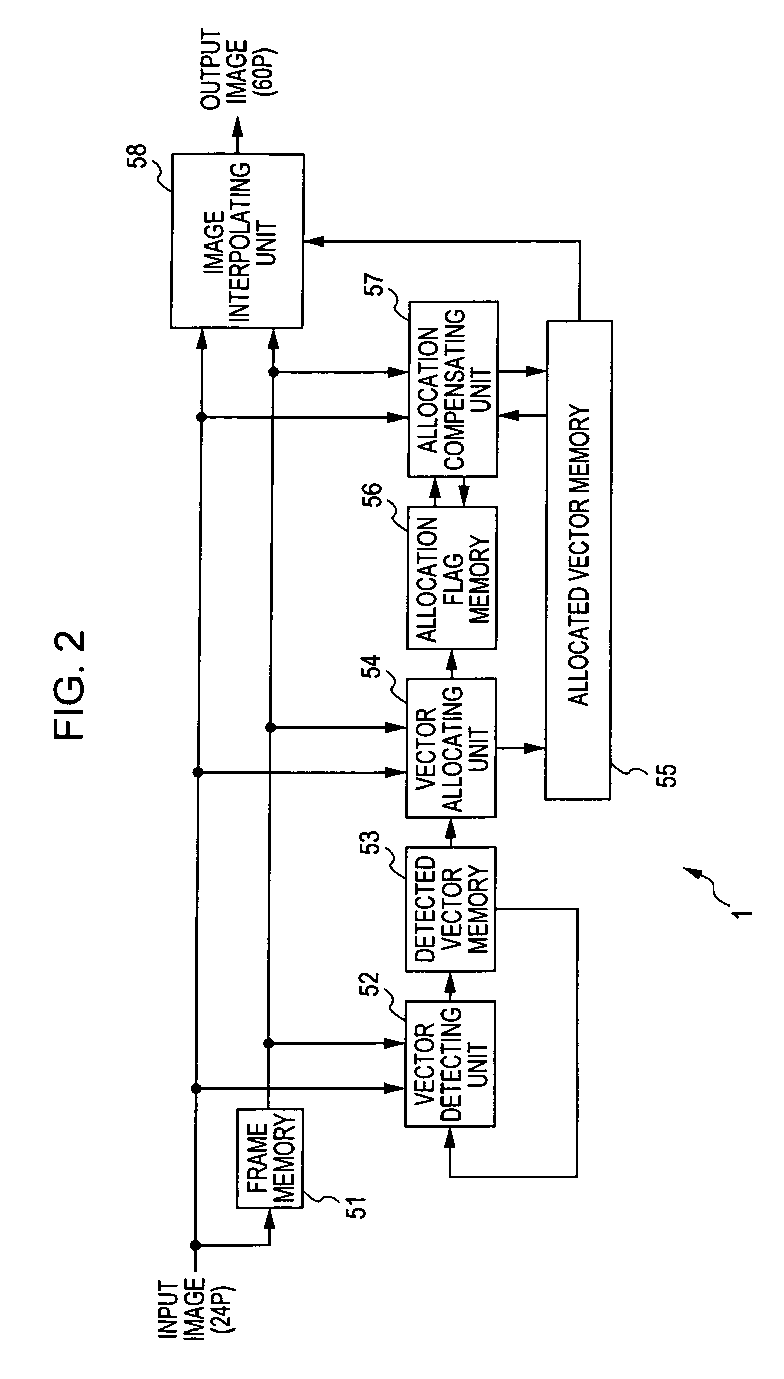
For each pixel in an operation block, an effective pixel determining unit sets a predetermined pixel difference (threshold value) on a time-base pixel difference. When the time-base pixel difference is less than the set predetermined pixel difference, it is determined that the pixel contributes to (or are effective in) motion vector detection, and uses the pixel in the gradient method in the case of performing motion vector detection. When the time-base pixel difference is not less than the set predetermined pixel difference, it is determined that the pixel is regarded as having a possibility to generate irregularity in movement, and the pixel is excluded from the gradient operation in the case of performing motion vector detection. The present invention is applicable to a signal processing apparatus for performing frame frequency conversion from a 24 P signal to a 60 P signal.

Description

BACKGROUND OF THE INVENTION [0001] 1. Field of the Invention [0002] The present invention relates to image processing apparatuses and methods, and recording media and programs used therewith. In particular, the present invention relates to an image processing apparatus and method that increase accuracy of motion vector detection, and to a recording medium and program used therewith. [0003] 2. Description of the Related Art [0004] In an image processing apparatus for converting the frame frequency of an image, the gradient method described in Japanese Unexamined Patent Application Publication No. 60-158786 is used as a method for detecting a motion vector in a block of interest. Although the gradient method has a feature capable of detecting a movement below pixel size by performing a simplified arithmetic operation, the method has bad accuracy for detection in units of pixels. Accordingly, in an ordinary case, it is common that motion vector detection is performed by accumulating de...

Claims


Application Information

Patent Timeline
IPC IPC(8): G06T3/40G06T7/20H04N5/14H04N7/01H04N7/12
CPCG06T3/4007H04N7/014H04N5/145G06T7/2053G06T7/254G06T1/00G06T7/00G06T7/20H04N7/01
Inventor HORISHI, TAKASHIYOSHIWARA, NORIFUMINAKAMURA, YUKIHIROKAINO, AKIHIKOKAWAGUCHI, KUNIOTAKAHASHI, YASUAKICHOKI, YUTAKONDO, TETSUJIRO
Owner SONY CORP
Learn More