Mobile wind-driven electric generating systems and method and apparatus

a technology of electric generating system and motor, which is applied in the direction of drilling pipes, caissons, artificial islands, etc., can solve the problems of high shear force, high labor intensity, and high cost, and achieve automatic and easy hydraulic jacked up, less expensive, and eliminated high tooth stress

Inactive Publication Date: 2005-11-24
INGLE JAMES E
View PDF24 Cites 32 Cited by
  • Summary
  • Abstract
  • Description
  • Claims
  • Application Information

AI Technical Summary

Benefits of technology

[0014] In one preferred aspect of the invention, a plurality of continuous linear motion motors are engaged with a plurality of supporting legs to provide continuous relative motion between the mobile offshore structure and its supporting legs, and to also maintain the mobile offshore structure and supporting legs locked in a stationary relationship. As used herein, the preferred “continuous linear motion motor,” refers to a plurality of hydraulic piston/cylinder units N whose piston operations are phased so that at most N−1 of the plurality of piston/cylinder units are engaged with a supporting leg and providing relative motion while at least one of the piston/cylinder units is disengaged from the supporting leg and being repositioned for re-engagement with the supporting leg to continue the relative motion. The preferred continuous linear motion motor thus permits a mobile offshore structure and wind-driven generator to be automatically and easily jacked up hydraulically with continuous motion.
[0015] In the preferred apparatus of the invention with a plurality of structure-supporting legs, a plurality of hydraulic piston/cylinder units are used to provide continuous relative motion of the mobile offshore structure with respect to a plurality of structure-supporting legs that carry a plurality of toothed racks, by phased operation of their pistons, that is, by sequentially engaging different groups of the piston/cylinder units with the plurality of toothed racks and driving their pistons with hydraulic pressure, while another group of the piston/cylinder units are disengaged from the toothed racks and are repositioned for reengagement by application of hydraulic pressure to the cylinders of the disengaged pistons. The pluralities of hydraulic piston/cylinders in their phased operations provide a plurality of continuous linear motion motors that can be controlled from the mobile offshore structure (or remotely) to jack the mobile offshore structure up or down, and to lock the mobile offshore structure in any stationary position. Such a plurality of continuous linear motion motors are substantially less expensive than a comparable plurality of spur gear drives, which can also be used to provide relative motion between the mobile offshore structure and its supporting legs.
[0016] In the preferred apparatus of the invention, a multiplicity of teeth are engaged in providing relative motion (and in lifting the mobile offshore structure) at any given moment of time, eliminating high tooth stress by spreading t

Problems solved by technology

This method of construction was labor-intensive, slow, and expensive.
Because the spur gears rotationally engage the toothed racks of the leg chords in raising and lowering the MODU supporting legs with respect to the MODU platform, the spur gear teeth and the teeth of the leg chord racks have cycloidal cross sections, and the spur gear drives are each engaged with the leg chord racks by line contact between a single tooth of the spur gear and a single mating tooth of a toothed rack, exposing the teeth of both the spur gear and the rack to extremely high shear forces and requiring that the spur gears and the toothed rack be made of an expensive high-grade steel, with a modulus of elasticity, for example, of 100,000 pounds per square inch (100 KSI).
In such systems, the plural spur gear drives are mounted vertically in sets of three units, one above another, so their pinion gears can engage the toothed racks that comprise the leg chords; however, the load is unequally shared by the plura

Method used


Image

  • Mobile wind-driven electric generating systems and method and apparatus
  • Mobile wind-driven electric generating systems and method and apparatus
  • Mobile wind-driven electric generating systems and method and apparatus

Examples


Embodiment Construction

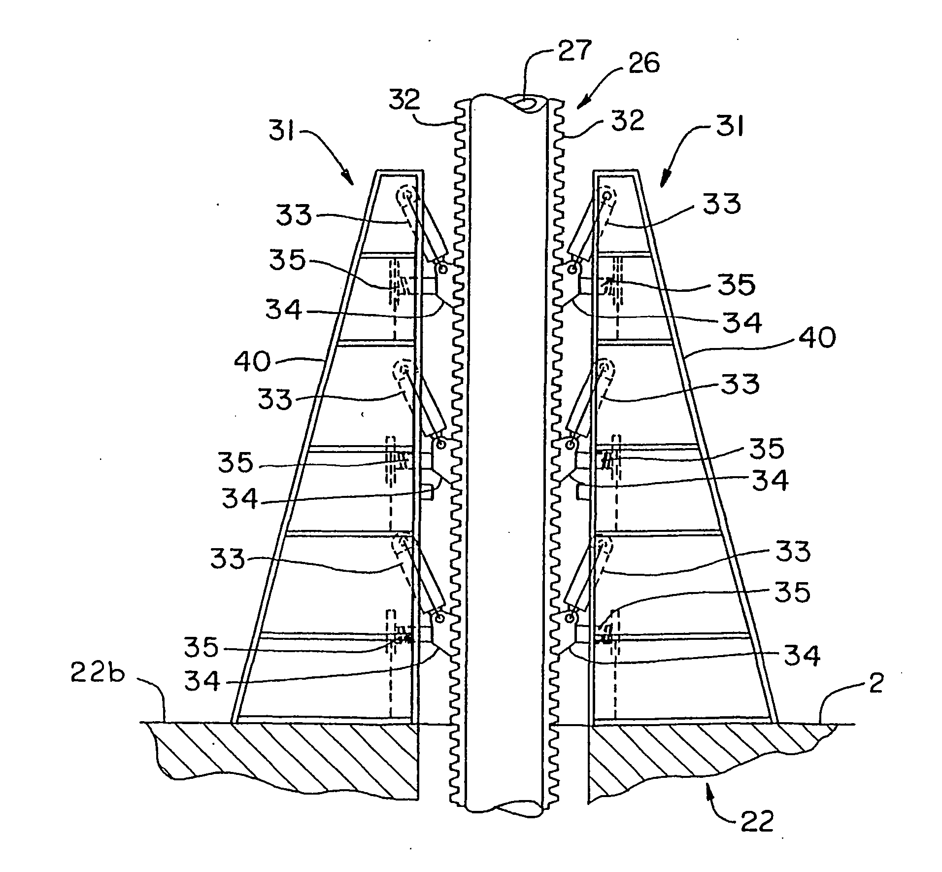
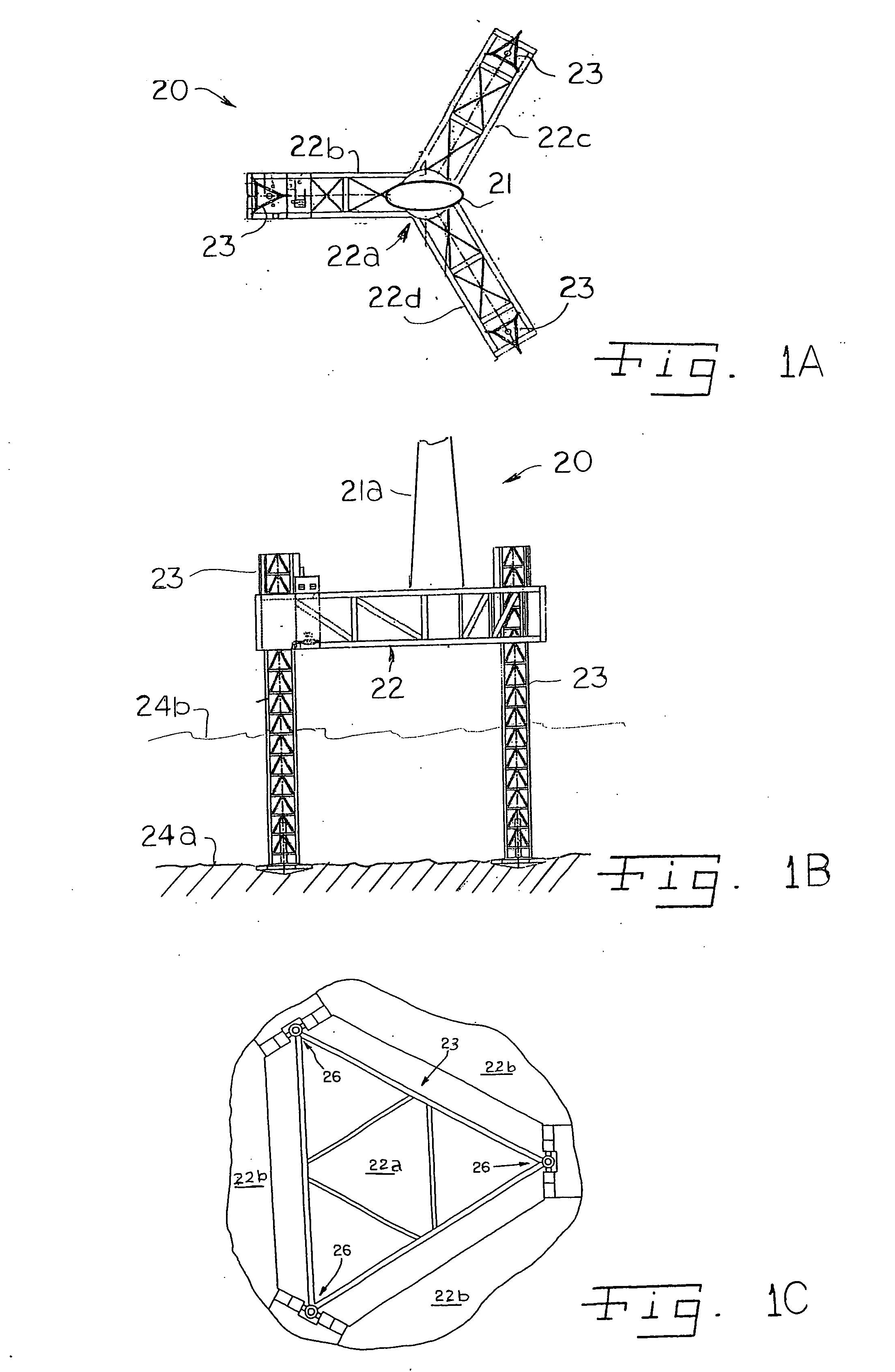
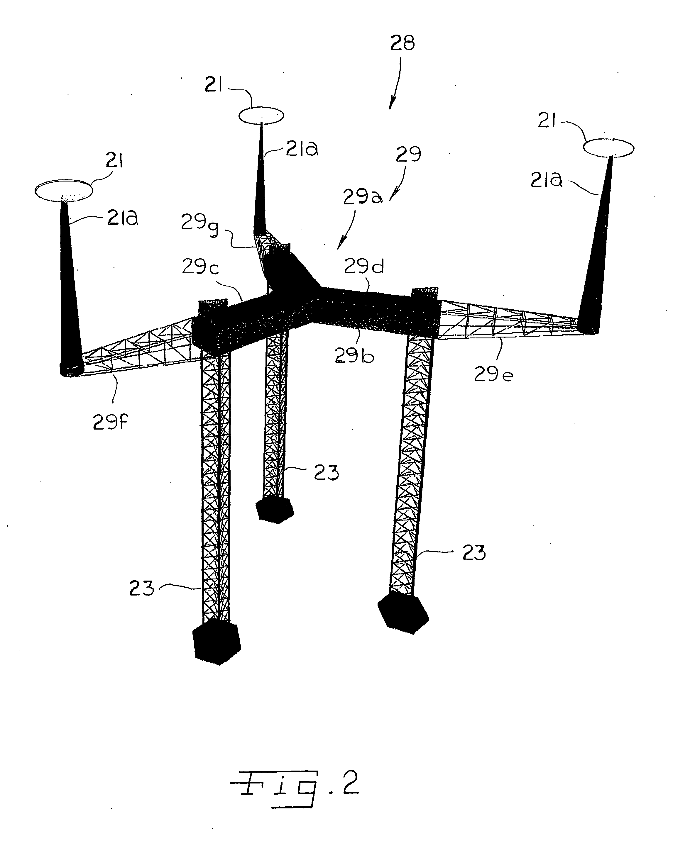
[0033]FIG. 1A and FIG. 1B illustrate a system and apparatus 20 for the offshore generation of electricity by means of a source of electricity, such as a wind-driven generator 21. FIG. 1A is a diagrammatic illustration of the system and apparatus 20 from the side, and FIG. 1B is a diagrammatic illustration of the system and apparatus 20 from above. As illustrated by FIGS. 1A and 1B, the apparatus comprises, in addition to the wind-driven generator 21 and its support 21a, a mobile structure 22 and a plurality of legs 23 for supporting the offshore structure 21 from the earth's surface 24a under the water. The supporting legs 23 movably engage the offshore structure 22 and the system and apparatus includes means to move the supporting legs 23 relative to the mobile structure 22, one preferred such means being illustrated in FIGS. 3-15 and described in greater detail below.

[0034] As illustrated in FIG. 1A, the mobile structure 22 is supported by the supporting legs 23 from the earth's ...


PUM


Abstract

A wind-driven source of electricity can be located and oriented to take advantage of winds traveling over water. A structure is provided that can be transported over water and carry one or more wind-driven sources of electricity and structure-supporting means for engaging the earth's surface under water. The structure is transported to an advantageous location for operation of the wind-driven sources of electricity; the structure supporting means is engaged with the earth's surface under water at the advantageous location; and the one or more wind-driven sources of electricity can be elevated to take advantage of the winds traveling over the water.

Description

RELATED APPLICATIONS [0001] This patent application is a continuation-in-part of U.S. patent application Ser. No. 10 / 978,510, filed Nov. 1, 2004, which is a divisional of U.S. patent application Ser. No. 10 / 720,657, filed Nov. 24, 2003, which is a divisional of U.S. patent application Ser. No. 09 / 835,794, filed Apr. 16, 2001, now U.S. Pat. No. 6,652,194 B1.FIELD OF THE INVENTION [0002] This invention relates to mobile wind-driven generating systems, and more particularly to systems, apparatus and methods by which wind-driven electric generators can be moved and located offshore to take best advantage of offshore and onshore winds. BACKGROUND OF THE INVENTION [0003] Offshore structures are not unknown. In 1955 the U.S. Army Corps. of Engineers constructed radar stations along the New England coast, which were commonly referred to as “Texas Towers.” In constructing these radar stations, the radar platforms were lifted on supporting legs, using hydraulic cylinders. While the legs and t...

Claims


Application Information

Patent Timeline
IPC IPC(8): E02B1/00E02B17/02E02B17/08E02D23/00
CPCE02B17/021E02B17/06E02B17/0818E02D27/42E02B17/0863E02B2017/006E02B2017/0082E02B17/0836
Inventor INGLE, JAMES E.HINES, DOUGLAS
Owner INGLE JAMES E
Why Eureka
Try Eureka