Surgical instrument

Inactive Publication Date: 2005-11-24
GYRUS MEDICAL LTD
View PDF0 Cites 1148 Cited by
  • Summary
  • Abstract
  • Description
  • Claims
  • Application Information

AI Technical Summary

Benefits of technology

[0013] Alternatively, the tissue-pulling device comprises a screw member rotatable with respect to the tube. Rotation of the screw member has the effect of pulling tissue into the tube. The tube preferably has an end face which is angled with respect to the longitudinal axis of the tube, conveniently at an angle of between 30 and 60 degre

Problems solved by technology

This rotation of the electrode necessitates a mechanical drive

Method used


Image

  • Surgical instrument
  • Surgical instrument
  • Surgical instrument

Examples


Example

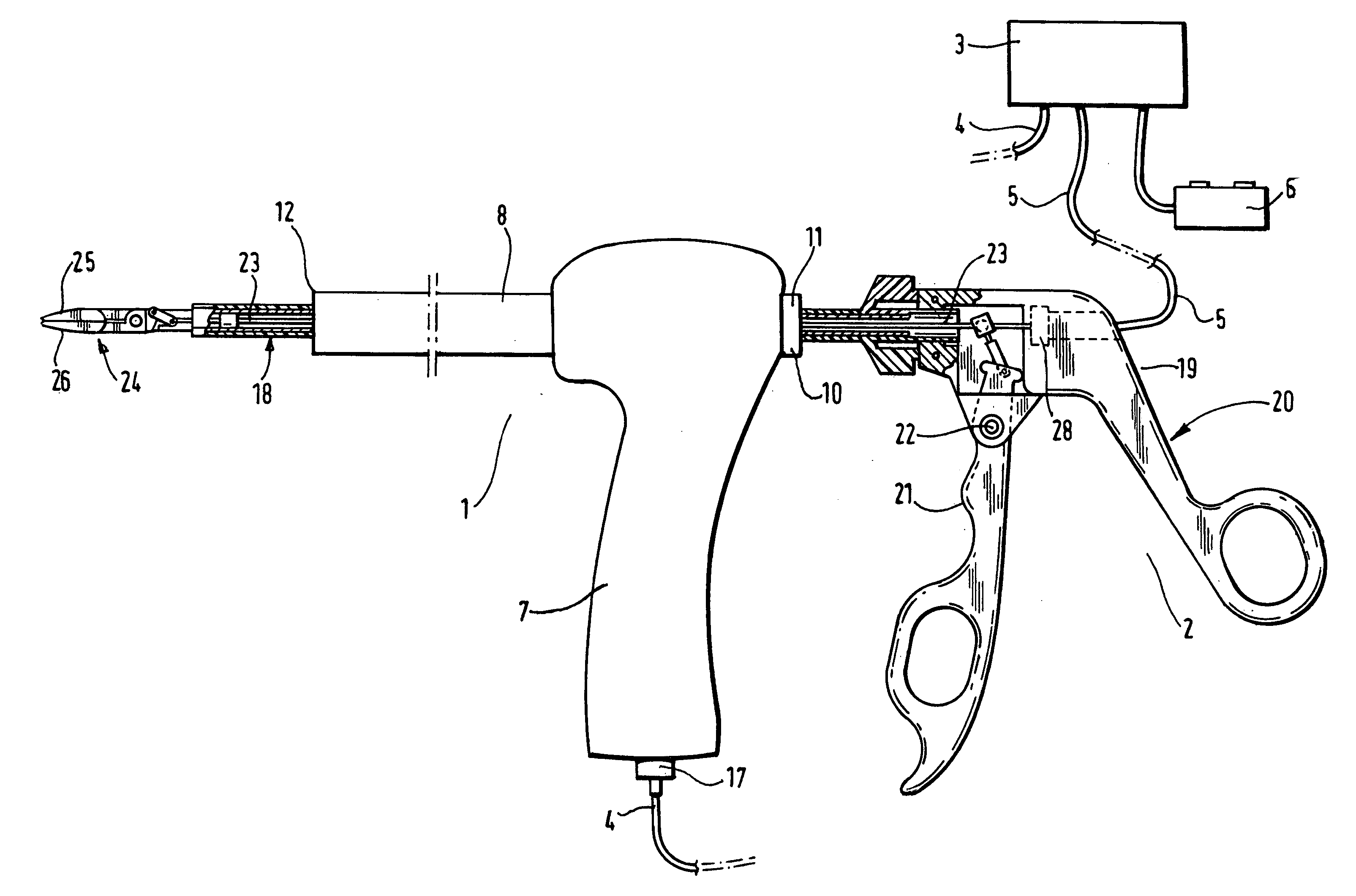
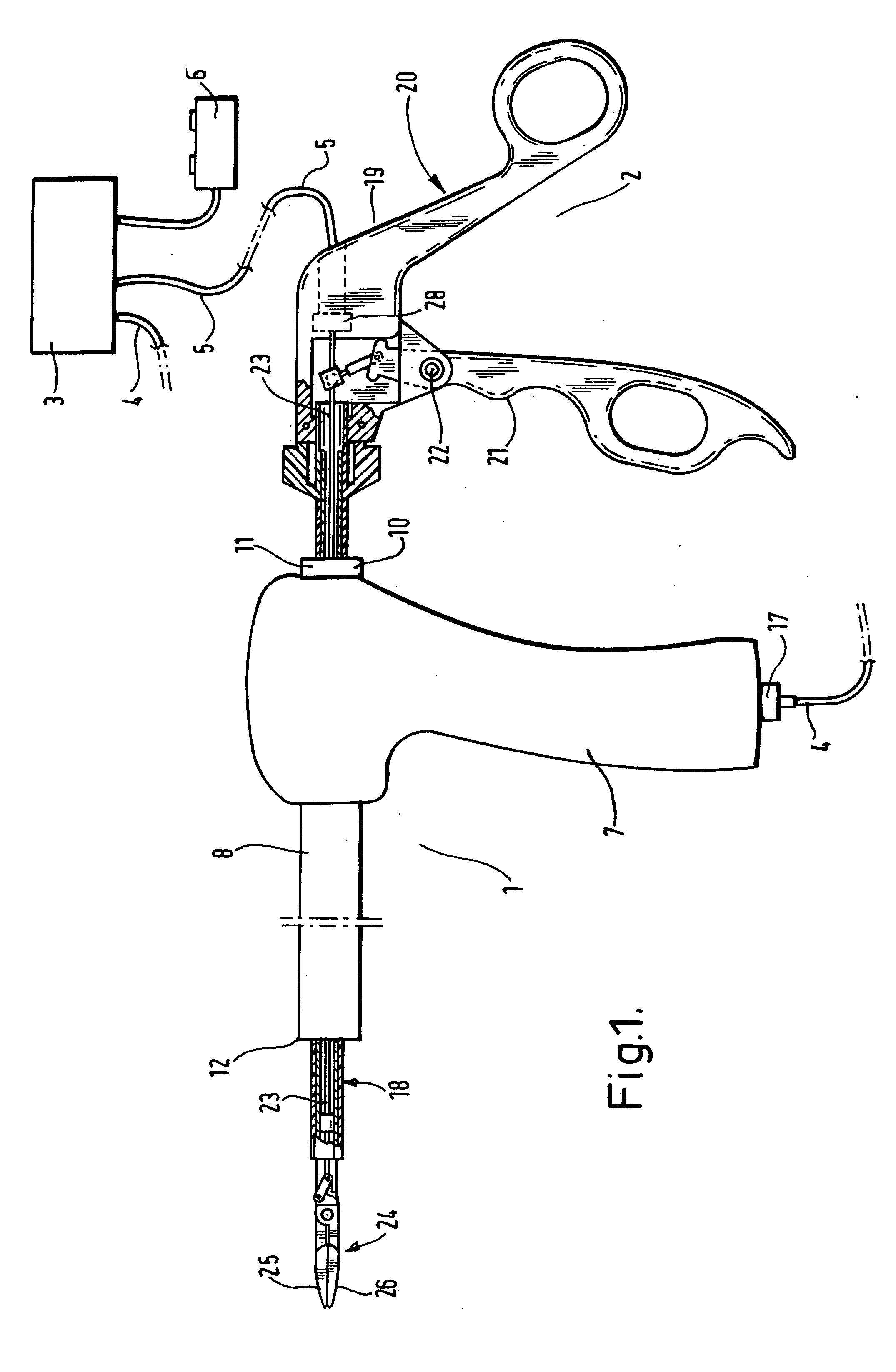
[0027] Referring to FIG. 1, a morcellating system comprises a morcellating device shown generally at 1, a tissue-pulling device shown generally at 2, and an electrosurgical generator 3. The generator 3 is connected to the morcellating device 1 by means of cable 4, and to the tissue-pulling device 2 by means of cable 5. The generator 3 is controlled by means of a footswitch 6.

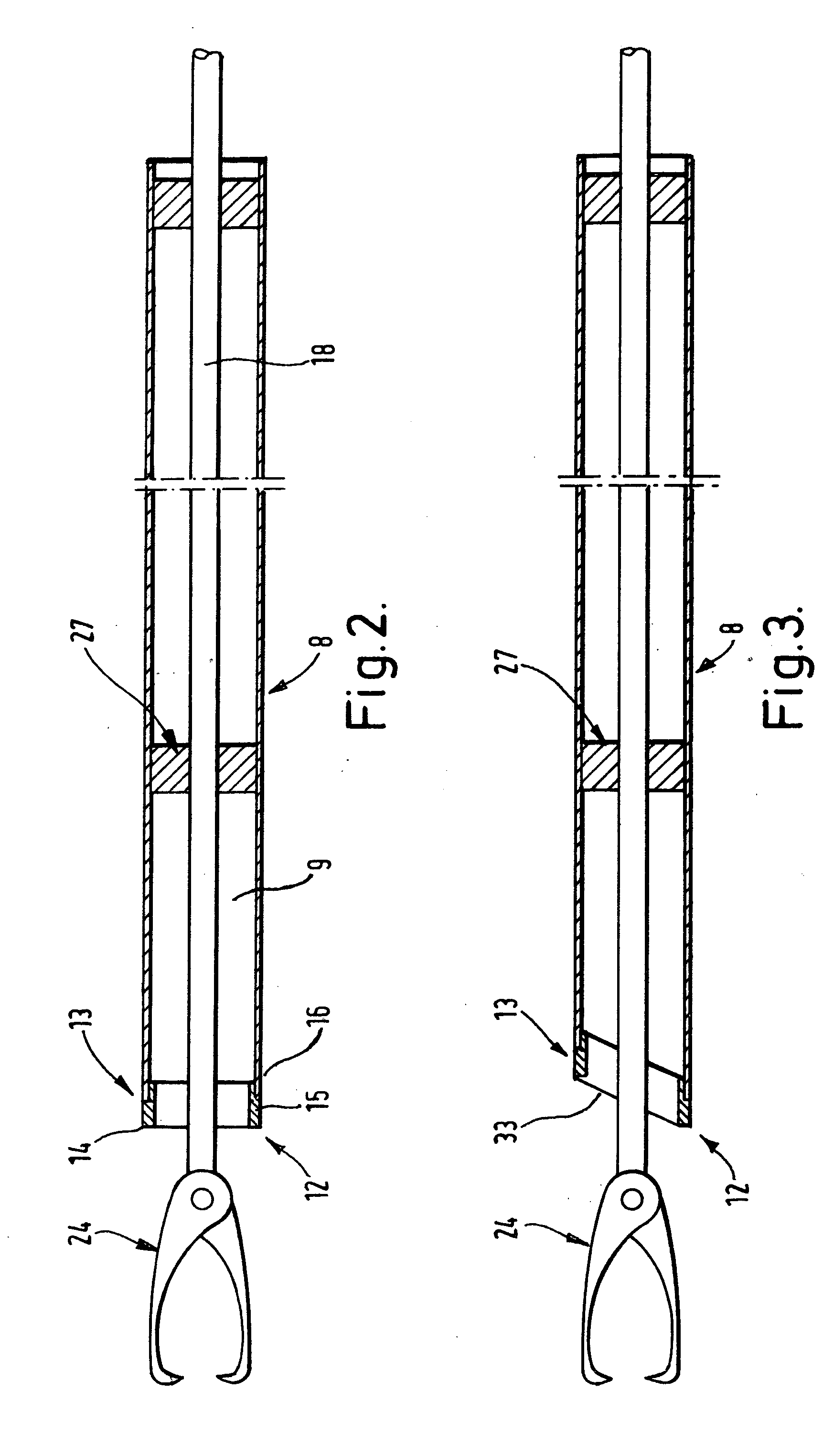
[0028] As shown in FIGS. 1 and 2, the morcellating device 1 comprises a handle 7 and a cylindrical tube 8. The cylindrical tube 8 is hollow, and defines a lumen 9 therein. The proximal end 10 of the tube 8 extends from the handle 7 as shown at 11, and the distal end 12 of the tube is provided with an electrosurgical electrode assembly 13. The electrosurgical electrode assembly 13 comprises an active tissue-cutting electrode 14, and an insulating member 15, both extending around the circumference of the tube 8. The insulating member 15 separates the electrode 14 from the remainder of the tube 8, which acts as a ...


PUM


Abstract

A device for morcellating tissue within a body cavity of a patient comprises a stationary tube having a distal end portion, and a bipolar electrosurgical electrode assembly located at the distal end of the tube. The electrosurgical electrode assembly comprises first and second electrodes separated by an insulation member, the bipolar electrosurgical electrode assembly extending around the circumference of the distal edge of the tube. When an electrosurgical cutting voltage is applied to the electrode assembly, and relative movement is initiated between the tube and the tissue, a core of severed tissue is formed within the tube such that it can be removed from the body cavity of the patient. A tissue-pulling device such as a jaw assembly can be employed to pull tissue against the distal end of the tube.

Description

BACKGROUND OF THE INVENTION [0001] This invention relates to a bipolar electrosurgical instrument for use in the bulk removal of tissue, as in a laparoscopic hysterectomy. [0002] In a laparoscopic hysterectomy, the body of the uterus is resected from the stump or fundus, and then removed from the operative site. To enable the uterus to be removed through a limited surgical opening, it is desirable to morcellate it into relatively smaller pieces of tissue, which are easier to remove. The present invention relates to an instrument and method for morcellating and removing a uterus. [0003] U.S. Pat. Nos. 5,957,884, 6,007,512 and 6,036,681 are examples of morcellating devices in which an element carrying an electrode is rotated in order to cause the morcellation of tissue. This rotation of the electrode necessitates a mechanical drive arrangement, which increases the complexity of the instrument. The present invention seeks to provide a simpler and hence more reliable arrangement for the...

Claims


Application Information

Patent Timeline
IPC IPC(8): A61B17/28A61B17/32A61B17/42A61B18/14
CPCA61B17/29A61B17/320016A61B17/32053A61B2018/1412A61B18/1485A61B2017/320775A61B2017/4216A61B18/1442
Inventor HALL, MATTHEW RICHARDMARSHALL, MARK GEORGEGOBLE, COLIN CHARLES OWENAMOAH, FRANCISVARNEY, KELVIN JOHNEBBUTT, JULIAN MARK
Owner GYRUS MEDICAL LTD
Why Eureka
Try Eureka