Apparatus and method for purifying thermoplastic polymers

Inactive Publication Date: 2012-05-10
KRONES AG
View PDF5 Cites 0 Cited by
  • Summary
  • Abstract
  • Description
  • Claims
  • Application Information

AI Technical Summary

Benefits of technology

[0012]Hence, some aspects of the disclosure are to provide an apparatus and a method for purifying thermoplastic polymers wherein foreign matter can be effectively separated without requiring much maintenance, and wherein the quality of the resulting polymer product is not lowered, even with inhomogeneous polymer reactants.

Problems solved by technology

The generated polymer flakes are, however, generally contaminated, i.e. they contain foreign matter which is usually separated during the extrusion and granulation process in order to improve the quality of the resulting polymer pellets so that the same can be used as a raw material for various high-quality products.
In this process, the problem arises that the filter becomes clogged / blocked with the ongoing operation of the extrusion apparatus, leading to a reduced flow rate of the polymer melt.
This causes a pressure build-up upstream of the filter and a pressure loss downstream thereof, which results in back pressures of up to 150 bar.
This, in turn, means that the filter is no longer operable and that a back washing, cleaning or replacement of the filter is required.
One of the causes for the clogging or blocking of the filter lies in the inhomogeneous consistency of the polymer melt which can contain constituent parts having a relatively high melting point so that the temperature of the polymer melt is so low that these constituent parts will deposit on the filter means as a solid polymer mass.
This, however, implies the disadvantage that simultaneously the temperature of the polymer melt across the whole extruder area also increases, leading to undesirable degradation reactions in temperature-sensitive polymers such as PET and thus deteriorates the quality of the resulting polymer pellets.
The apparatuses and methods disclosed in prior art generally have the drawback that the filter for separating foreign matter from the polymer melt rapidly becomes blocked or clogged so that it must be frequently replaced.
Furthermore, the systems known from prior art do not allow cleaning of the filters during an ongoing operation without impairing the quality of the resulting polymer product, i.e. in the methods according to prior art, particularly in the case of inhomogeneous polymer reactants, maintenance is frequently required.

Method used


Image

  • Apparatus and method for purifying thermoplastic polymers
  • Apparatus and method for purifying thermoplastic polymers
  • Apparatus and method for purifying thermoplastic polymers

Examples


Embodiment Construction

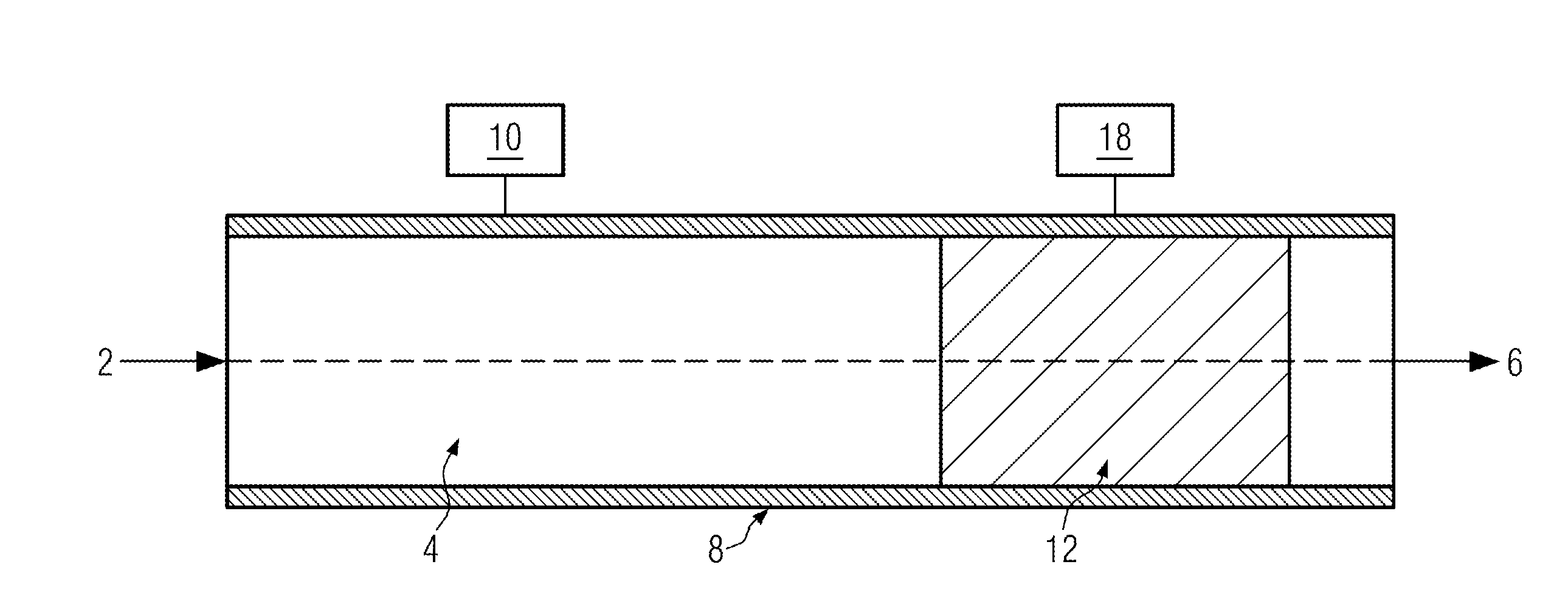
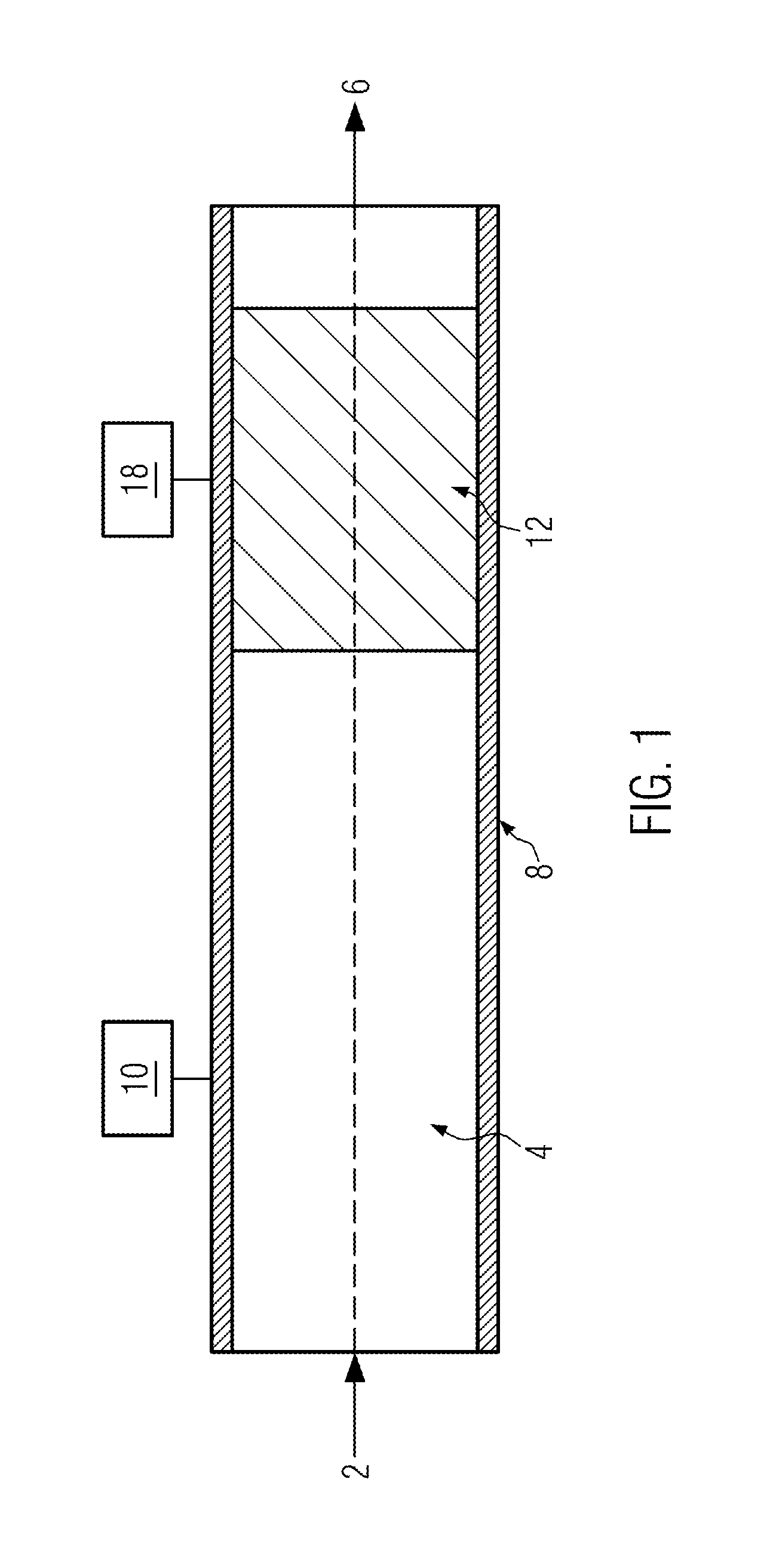
[0036]FIG. 1 schematically shows an apparatus for purifying thermoplastic polymers, comprising a means 8 for generating and conveying a polymer melt 4, the polymer melt 4 being contained therein. The means 8 includes a first heating unit 10 for heating the polymer melt 4 flowing through in the direction of arrow 2. Furthermore, within the means 8 a filter means 12 is contained comprising, according to the disclosure, a second, separate heating unit 18 by means of which the temperature of the filter can be set independently from the temperature of the polymer melt.

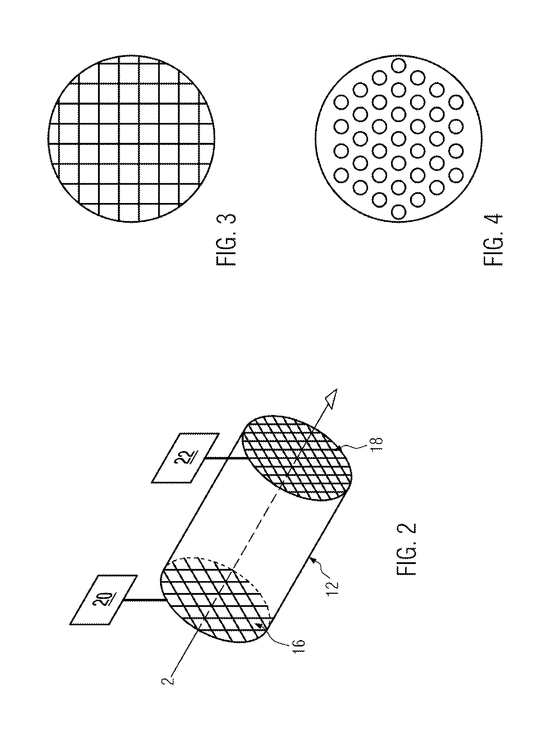
[0037]FIG. 2 shows a preferred embodiment of filter means 12. In this configuration, the filter means comprises a particle filter 16 and a micro-sieve 18 in an arrangement in which the polymer melt first passes the particle filter 16 and then the micro-sieve 18. Furthermore, the particle filter 16 and the micro-sieve 18 each have a separate heating unit 20 and 22, respectively, serving to set the temperatures of the particl...


PUM

PropertyMeasurementUnit
Temperatureaaaaaaaaaa

Abstract

An apparatus for purifying thermoplastic polymers, including a means for generating and conveying a polymer melt, the means including a first heating unit and a filter means, and the filter means including a second heating unit. And a method for purifying thermoplastic polymers, including a step of filtering a polymer melt by way of a filter means, wherein the filter means is at least temporarily heated to a temperature which is higher than that of the polymer melt.

Description

CROSS-REFERENCE TO RELATED APPLICATION[0001]The present application claims the benefit of priority of German Application No. 102010042967.8, filed Oct. 26, 2010. The entire text of the priority application is incorporated herein by reference in its entirety.FIELD OF THE DISCLOSURE[0002]This disclosure relates to an apparatus and a method for purifying thermoplastic polymers and in particular to the purification of to-be-recycled packaging materials made of thermoplastic polymers.BACKGROUND[0003]Against the background of the scarcity of fossil raw materials, packaging materials, most of which are made of polymers based on petrol, are increasingly being recycled nowadays. Examples of thermoplastic polymers are, among others, polyester, polyolefins, polystyrenes, polyamides or polycarbonates, in particular PET, or copolymers thereof. During the recycling process, the packaging materials are generally collected after having been used, sorted according to the type of material by means of...

Claims


Application Information

Patent Timeline
IPC IPC(8): B01D35/18B01D37/04B01D35/02B29C48/03B29C48/08B29C48/693B29C48/92
CPCB29B17/02B29C47/0009B29C47/0021B29C47/686B29C47/92B29C2947/92019B01D37/04B29C2947/9238B29C2947/92514B29C2947/92704B29C2947/92876B29K2105/065B29C2947/92209B29C48/92B29C2948/92209B29C2948/92704B29C2948/92876B29C48/03B29C48/08B29C48/693B29C2948/92019B29C2948/9238B29C2948/92514Y02W30/62
Inventor FRIEDLAENDER, THOMASWASMUHT, KLAUS-KARLZACHARIAS, JORGMAYR, STEPHAN
Owner KRONES AG
Why Eureka
Try Eureka