
Trigonometric wave generation circuit using series expansion

a trigonometric wave and series expansion technology, applied in the field of trigonometric wave generation circuits, can solve the problems of increasing power consumption and enlarged circuit scale, and achieve the effect of reducing circuit area

Inactive Publication Date: 2005-11-24
ROHM CO LTD
View PDF4 Cites 152 Cited by
  • Summary
  • Abstract
  • Description
  • Claims
  • Application Information

AI Technical Summary

Benefits of technology

[0011] The operator may further comprise a memory which retains coefficients of the terms of the series expansion of the trigonometric function. The operator may perform the operation after bounding the phase value of the trigonometric function to a range from −½π to ½π by a shift operation. By bounding the phase value that varies from −π to π to a range from −π / 2 to π / 2, it is ensured that the absolute value of the independent variable of the trigonometric function is small so that an error of the dependent variable of the generated trigonometric function is reduced.
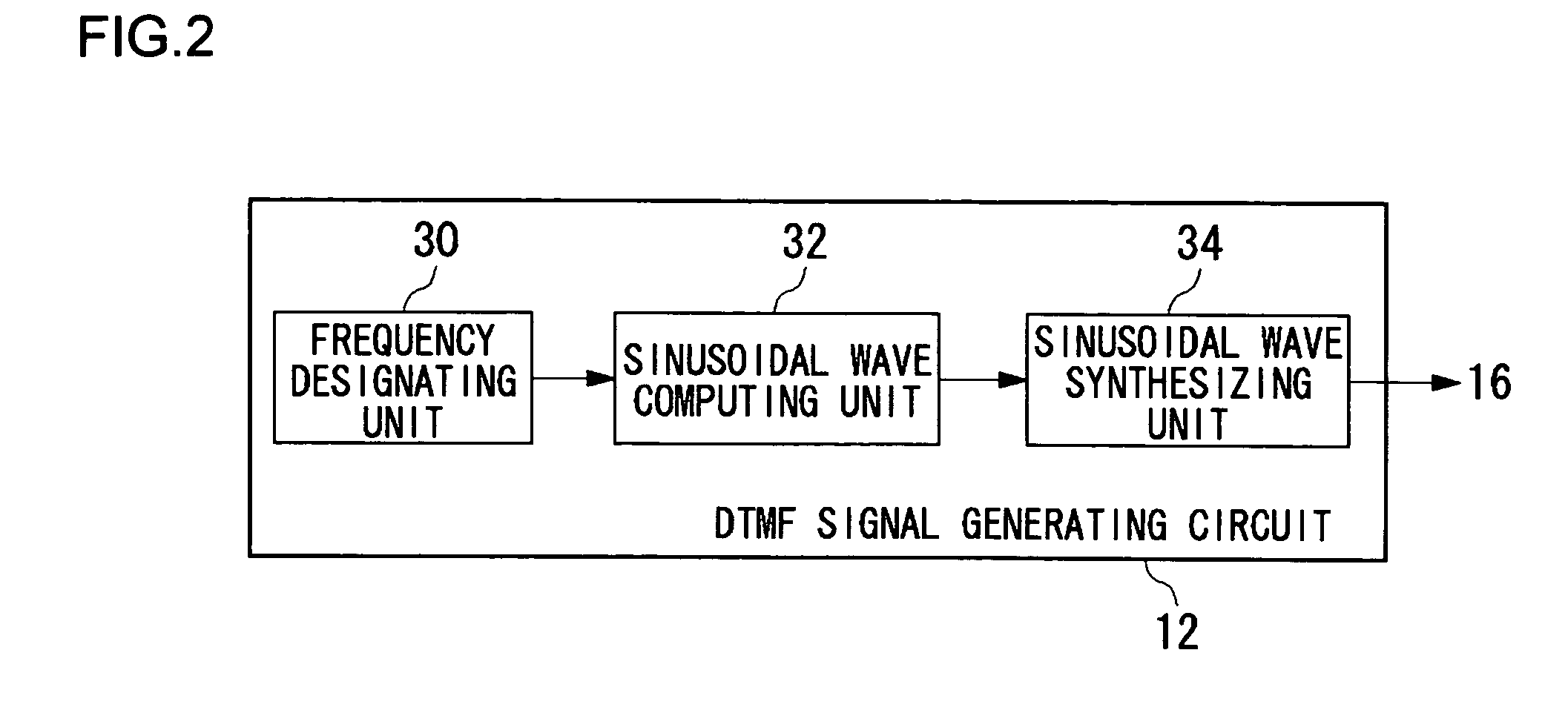
[0013] The first frequency sinusoidal wave generating unit and the second frequency sinusoidal wave generating unit may be formed to share a single trigonometric wave generating circuit. The DTMF signal generating circuit may further comprise a frequency designating unit which designates the first frequency and the second frequency to the single trigonometric wave generating circuit. Since the single trigonometric wave generating circuit is capable of computing trigonometric waves at the first frequency and the second frequency, the circuit area is reduced.
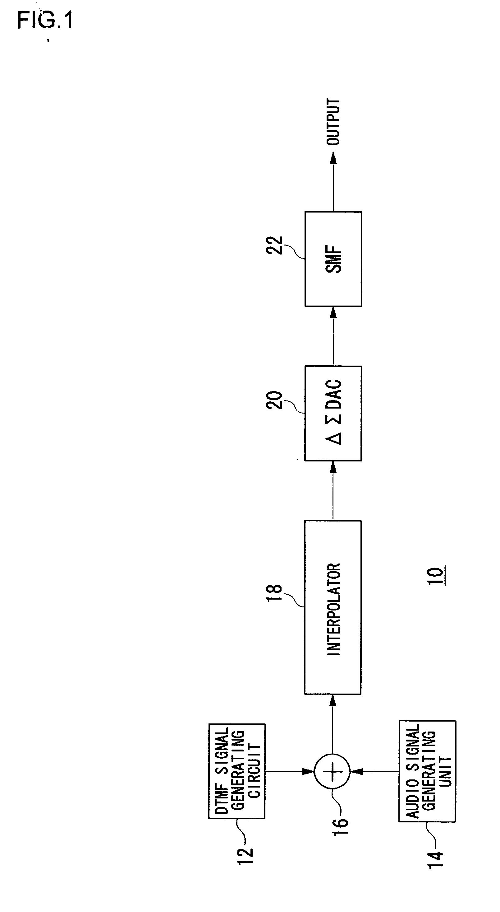
[0015] The sound signal generating circuit may further comprise: an interpolator which interpolates between values of the sound signal mixed by the mixing unit; a ΔΣ D / A converter which subjects an output signal from the interpolator to digital-to-analog conversion; and a filter provided in a stage subsequent to the ΔΣ D / A converter. By performing ΔΣ modulation and oversampling, noise shaping is effected and high-quality sound is obtained.

Problems solved by technology

Therefore, the circuit scale tends to be enlarged and power consumption tends to be increased.

Method used


Image

  • Trigonometric wave generation circuit using series expansion
  • Trigonometric wave generation circuit using series expansion
  • Trigonometric wave generation circuit using series expansion

Examples


Embodiment Construction

[0024] The invention will now be described based on preferred embodiments which do not intend to limit the scope of the present invention but exemplify the invention. All of the features and the combinations thereof described in the embodiment are not necessarily essential to the invention.

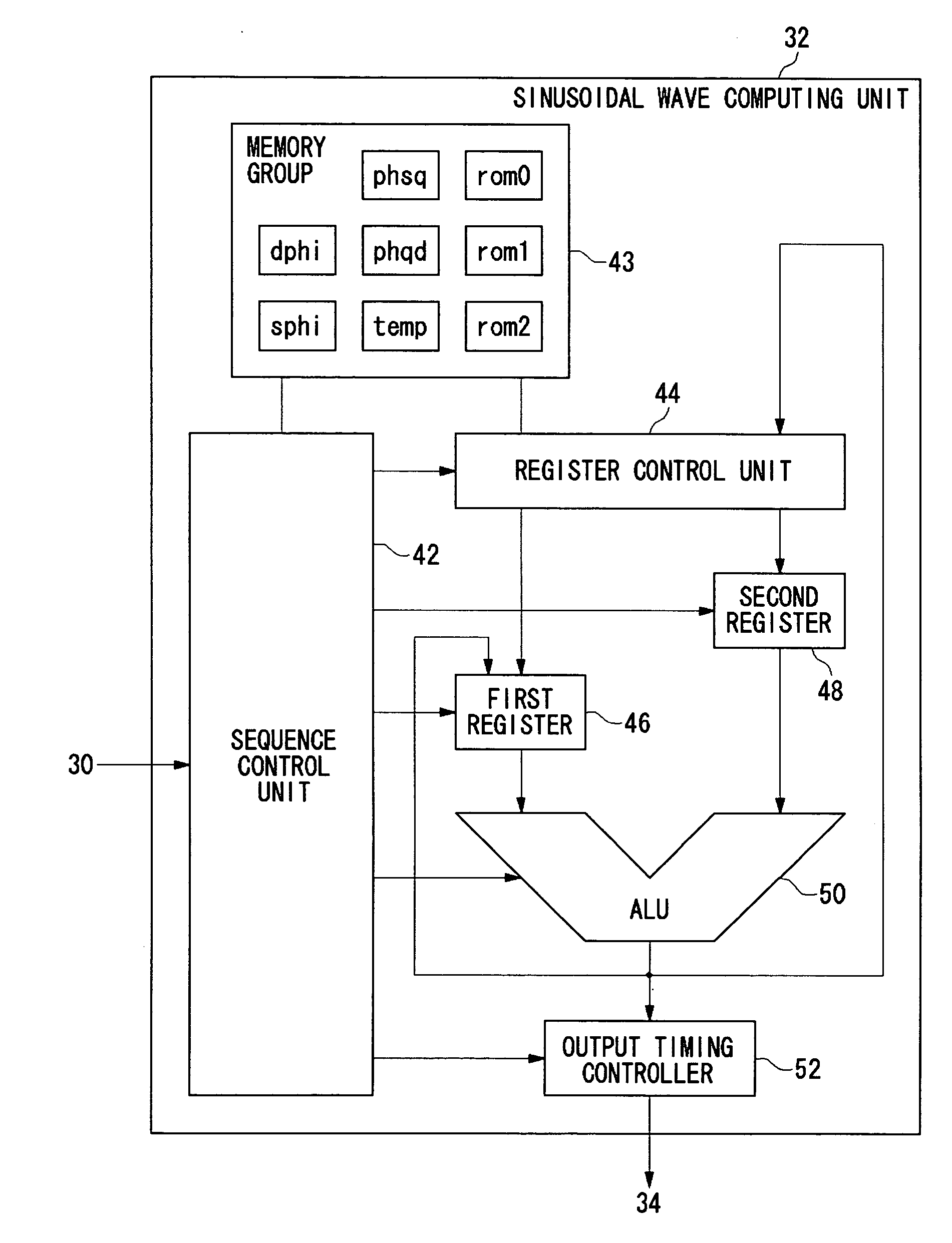
[0025] According to an embodiment of the present invention that will be described below, a sinusoidal wave is computed promptly and with precision, by determining each of the terms of a Taylor expansion of a sinusoidal function by direct arithmetic operation that uses hardware.

[0026]FIG. 1 is a block diagram illustrating the overall structure of a sound signal generating circuit 10. The sound signal generating circuit 10 is provided with a DTMF signal generating circuit 12 that generates a digital DTMF signal, an audio signal generating unit 14 that generates a digital audio signal related to audio, and a mixing unit 16 that generates a digital audio / DTMF signal by mixing the DTMF signal and the...


PUM


Abstract

A DTMF signal generating circuit is provided with a frequency designating unit which designates frequencies to form a DTMF signal, a sinusoidal wave computing unit which computes sinusoidal waves by referring to frequencies designated by the frequency designating unit, and a sinusoidal wave synthesizing unit which synthesizes two sinusoidal waves computed by the sinusoidal wave computing unit. The sinusoidal wave computing unit is provided with operators such as an adder-subtracter and a multiplier and generates a sinusoidal wave by determining terms of a Taylor expansion of a sinusoidal function by arithmetic operation.

Description

BACKGROUND OF THE INVENTION [0001] 1. Field of the Invention [0002] The present invention relates to a circuit for generating a trigonometric wave such as a sinusoidal wave and, more particularly, to a circuit applicable to a circuit for generating a DTMF signal using a sinusoidal wave. [0003] 2. Description of the Related Art [0004] Signals such as sinusoidal waves represented by trigonometric functions are used in a variety of fields. For example, a Dual Tone Multi-Frequency (DTMF) signal used as a dial signal in a touch-tone system is generated by combining sinusoidal waves at two frequencies. The technology for generating a trigonometric wave such as a sinusoidal wave by converting a digital signal into an analog signal is known in the related art. For example, patent document No. 1 discloses a circuit that reads sinusoidal waveform data from a sinusoidal wave data table so as to generate a digital DTMF signal and convert the DTMF signal into an analog signal by a D / A converter....

Claims


Application Information

Patent Timeline
IPC IPC(8): G06F1/02H04L27/30
CPCH04L27/30G06F1/022H03B28/00H04L27/26
Inventor IINO, YUKINOBUKURIHARA, NAOKI
Owner ROHM CO LTD
Learn More